Canon EOS C300 Mark III EOS C300 Mark III EOS C500 Mark II Instruction Manual - Page 97
Synchronizing with an External Device, Connecting an External Device, Time Code Signal Input
 |
View all Canon EOS C300 Mark III manuals
Add to My Manuals
Save this manual to your list of manuals |
Page 97 highlights
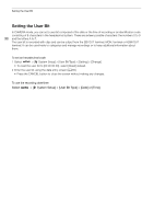
Synchronizing with an External Device Synchronizing with an External Device In CAMERA mode, you can use the camera's TIME CODE terminal to synchronize this camera's time code to an external signal. Using the same external time code signal with multiple cameras allows you to set up a multi- camera recording. You can also output the time code signal from this camera to other cameras. You can output 97 the time code signal from the SDI OUT terminal or MON. terminal to an editing device (while recording or during playback), so the editor can create video with the same time code. Additionally, when the optional EU-V1 Expansion Unit 1 or EU-V2 Expansion Unit 2 is attached to the camera, you can use the EU-V1 or EU-V2's G-LOCK/SYNC OUT terminal to synchronize this camera's video signal to a reference signal* from an external video device (Genlock synchronization) or to send out the camera's video signal as a synchronization reference signal*. * As reference video signal (input signal) for Genlock synchronization, you can use an analog blackburst or tri-level HD signal. The reference video output signal will be a tri-level HD signal. Connecting an External Device When synchronizing a time code signal, connect the external device to the TIME CODE terminal on the camera. When synchronizing with a reference video signal, connect the external device to the G-LOCK/SYNC OUT terminal on an optional EU-V1 or EU-V2 attached to the camera. Be sure to set either terminal to input or output in advance. Connection diagram TIME CODE terminal EU-V2 Expansion Unit 2 (optional) G-LOCK/SYNC OUT terminal BNC cable (commercially available) Time Code Signal Input An external SMPTE-standard LTC timing signal received from the TIME CODE terminal can be recorded as the time code. The user bit of the external timing signal can also be recorded with clips. Before connecting the device, set the TIME CODE terminal to input with the procedure below and make sure the time code running mode is set to [Free Run] (A 94). 1 Select > [B System Setup] > [TC In/Out] > [In]. 2 To record the external time code signal's user bit, select also Recording Mode] > [External]. > [B System Setup] > [User Bit
-
 1
1 -
2
-
3
-
4
-
5
-
6
-
7
-
8
-
9
-
10
-
11
-
12
-
13
-
14
-
15
-
16
-
17
-
18
-
19
-
20
-
21
-
22
-
23
-
24
-
25
-
26
-
27
-
28
-
29
-
30
-
31
-
32
-
33
-
34
-
35
-
36
-
37
-
38
-
39
-
40
-
41
-
42
-
43
-
44
-
45
-
46
-
47
-
48
-
49
-
50
-
51
-
52
-
53
-
54
-
55
-
56
-
57
-
58
-
59
-
60
-
61
-
62
-
63
-
64
-
65
-
66
-
67
-
68
-
69
-
70
-
71
-
72
-
73
-
74
-
75
-
76
-
77
-
78
-
79
-
80
-
81
-
82
-
83
-
84
-
85
-
86
-
87
-
88
-
89
-
90
-
91
-
 92
92 -
 93
93 -
 94
94 -
 95
95 -
 96
96 -
 97
97 -
 98
98 -
 99
99 -
 100
100 -
 101
101 -
 102
102 -
103
-
104
-
105
-
106
-
107
-
108
-
109
-
110
-
111
-
112
-
113
-
114
-
115
-
116
-
117
-
118
-
119
-
120
-
121
-
122
-
123
-
124
-
125
-
126
-
127
-
128
-
129
-
130
-
131
-
132
-
133
-
134
-
135
-
136
-
137
-
138
-
139
-
140
-
141
-
142
-
143
-
144
-
145
-
146
-
147
-
148
-
149
-
150
-
151
-
152
-
153
-
154
-
155
-
156
-
157
-
158
-
159
-
160
-
161
-
162
-
163
-
164
-
165
-
166
-
167
-
168
-
169
-
170
-
171
-
172
-
173
-
174
-
175
-
176
-
177
-
178
-
179
-
180
-
181
-
182
-
183
-
184
-
185
-
186
-
187
-
188
-
189
-
190
-
191
-
192
-
193
-
194
-
195
-
196
-
197
-
198
-
199
-
200
-
201
-
202
-
203
-
204
-
205
-
206
-
207
-
208
-
209
-
210
-
211
-
212
-
213
-
214
-
215
-
216
-
217
-
218
-
219
-
220
-
221
-
222
-
223
-
224
-
225
-
226
-
227
-
228
-
229
-
230
-
231
-
232
-
233
-
234
-
235
-
236
-
237
-
238
-
239
-
240
-
241
-
242
-
243
-
244
-
245
-
246
-
247
 |
 |
