Canon PC720 Service Manual - Page 101
Power, Supply, Circuit
 |
View all Canon PC720 manuals
Add to My Manuals
Save this manual to your list of manuals |
Page 101 highlights
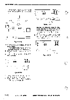
OPERATIONS AND TIMINGIIIIIIII B. Power Supply Circuit The copier's power supply assembly consists of its DC power supply, scanning lamp power supply, and composite power supply circuit, and uses a single main transfer (T101) to supply high voltage. The copier's power supply is equipped with a microprocessor for exchange of data with the DC controller PCB. The copier's power switch is a soft switch, and the copier is equipped with an auxiliary power supply to drive the soft switch. The auxiliary power supply provides the microprocessor (Q900) with +5V power while the power plug is connected and the door switch (DS1) is on. AC power is supplied to the DC power supply assembly when the door switch (DS1) and the power switch on the control panel are turned on. The DC power supply generates +5 V, +24 VR, and +24 VU for the DC controller PCB. When the power switch is turned off, power to the DC controller PCB is cut; to back up data on error codes (E000, E001, E002, E003), the copier uses the capacitor (C123) located within the DC controller circuit. When any of these codes (E000, E001, E002, E003) occurs, charges are stored in the capacitor (C123). The copier indicates `E0' on the control panel if charges exist in the capacitor when the power switch is turned on to indicate that an error associated with the fixing heater is present. Caution: The back-up capacitor (C123) keeps charges for about 5 min after the power switch is turned off. Reference: The tolerances allowed for the DC voltage are as follows: • +5 V ±5% • +24 VR ±5% • +24 VU ±12.5% However, the above values apply on the condition that the AC input tolerances are between -15% and +10°/0. COPYRIGHT © 1994 CANON INC. CANON PC720/14017501770 REVD AUG. 1994 PRINTED IN JAPAN ompRat AU JAPON) 3 - 61
-
 1
1 -
2
-
3
-
4
-
5
-
6
-
7
-
8
-
9
-
10
-
11
-
12
-
13
-
14
-
15
-
16
-
17
-
18
-
19
-
20
-
21
-
22
-
23
-
24
-
25
-
26
-
27
-
28
-
29
-
30
-
31
-
32
-
33
-
34
-
35
-
36
-
37
-
38
-
39
-
40
-
41
-
42
-
43
-
44
-
45
-
46
-
47
-
48
-
49
-
50
-
51
-
52
-
53
-
54
-
55
-
56
-
57
-
58
-
59
-
60
-
61
-
62
-
63
-
64
-
65
-
66
-
67
-
68
-
69
-
70
-
71
-
72
-
73
-
74
-
75
-
76
-
77
-
78
-
79
-
80
-
81
-
82
-
83
-
84
-
85
-
86
-
87
-
88
-
89
-
90
-
91
-
92
-
93
-
94
-
95
-
 96
96 -
 97
97 -
 98
98 -
 99
99 -
 100
100 -
 101
101 -
 102
102 -
 103
103 -
 104
104 -
 105
105 -
 106
106 -
107
-
108
-
109
-
110
-
111
-
112
-
113
-
114
-
115
-
116
-
117
-
118
-
119
-
120
-
121
-
122
-
123
-
124
-
125
-
126
-
127
-
128
-
129
-
130
-
131
-
132
-
133
-
134
-
135
-
136
-
137
-
138
-
139
-
140
-
141
-
142
-
143
-
144
-
145
-
146
-
147
-
148
-
149
-
150
-
151
-
152
-
153
-
154
-
155
-
156
-
157
-
158
-
159
-
160
-
161
-
162
-
163
-
164
-
165
-
166
-
167
-
168
-
169
-
170
-
171
-
172
-
173
-
174
-
175
-
176
-
177
-
178
-
179
-
180
-
181
-
182
-
183
-
184
-
185
-
186
-
187
-
188
-
189
-
190
-
191
-
192
-
193
-
194
-
195
-
196
-
197
-
198
-
199
-
200
 |
 |