Canon PC720 Service Manual - Page 59
Controlling, Scanning
 |
View all Canon PC720 manuals
Add to My Manuals
Save this manual to your list of manuals |
Page 59 highlights
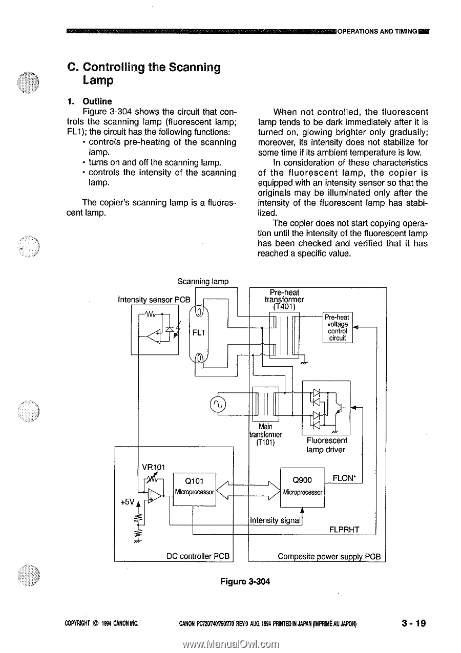
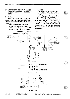
OPERATIONS AND TIMING= C. Controlling the Scanning Lamp 1. Outline Figure 3-304 shows the circuit that con- trols the scanning lamp (fluorescent lamp; FL1); the circuit has the following functions: • controls pre-heating of the scanning lamp. • turns on and off the scanning lamp. • controls the intensity of the scanning lamp. The copier's scanning lamp is a fluorescent lamp. When not controlled, the fluorescent lamp tends to be dark immediately after it is turned on, glowing brighter only gradually; moreover, its intensity does not stabilize for some time if its ambient temperature is low. In consideration of these characteristics of the fluorescent lamp, the copier is equipped with an intensity sensor so that the originals may be illuminated only after the intensity of the fluorescent lamp has stabilized. The copier does not start copying operation until the intensity of the fluorescent lamp has been checked and verified that it has reached a specific value. Scanning lamp Intensity sensor PCB ""At'Ar- •- Pre-heat transformer (T401) Pre-heat voltage control circuit VR101 +5V Q101 Microprocessor Main transformer (T101) Fluorescent lamp driver Q900 FLON* icroprocessor Intensity signal FLPRHT DC controller PCB Composite power supply PCB Figure 3-304 COPYRIGHT © 1994 CANON INC. CANON PC720t740R50/770 REV.O AUG.1994 PRINTED IN JAPAN fMPRIME AU JAPAN) 3- 19
-
 1
1 -
2
-
3
-
4
-
5
-
6
-
7
-
8
-
9
-
10
-
11
-
12
-
13
-
14
-
15
-
16
-
17
-
18
-
19
-
20
-
21
-
22
-
23
-
24
-
25
-
26
-
27
-
28
-
29
-
30
-
31
-
32
-
33
-
34
-
35
-
36
-
37
-
38
-
39
-
40
-
41
-
42
-
43
-
44
-
45
-
46
-
47
-
48
-
49
-
50
-
51
-
52
-
53
-
 54
54 -
 55
55 -
 56
56 -
 57
57 -
 58
58 -
 59
59 -
 60
60 -
 61
61 -
 62
62 -
 63
63 -
 64
64 -
65
-
66
-
67
-
68
-
69
-
70
-
71
-
72
-
73
-
74
-
75
-
76
-
77
-
78
-
79
-
80
-
81
-
82
-
83
-
84
-
85
-
86
-
87
-
88
-
89
-
90
-
91
-
92
-
93
-
94
-
95
-
96
-
97
-
98
-
99
-
100
-
101
-
102
-
103
-
104
-
105
-
106
-
107
-
108
-
109
-
110
-
111
-
112
-
113
-
114
-
115
-
116
-
117
-
118
-
119
-
120
-
121
-
122
-
123
-
124
-
125
-
126
-
127
-
128
-
129
-
130
-
131
-
132
-
133
-
134
-
135
-
136
-
137
-
138
-
139
-
140
-
141
-
142
-
143
-
144
-
145
-
146
-
147
-
148
-
149
-
150
-
151
-
152
-
153
-
154
-
155
-
156
-
157
-
158
-
159
-
160
-
161
-
162
-
163
-
164
-
165
-
166
-
167
-
168
-
169
-
170
-
171
-
172
-
173
-
174
-
175
-
176
-
177
-
178
-
179
-
180
-
181
-
182
-
183
-
184
-
185
-
186
-
187
-
188
-
189
-
190
-
191
-
192
-
193
-
194
-
195
-
196
-
197
-
198
-
199
-
200
 |
 |