Canon PC720 Service Manual - Page 135
Mechanical, System, Copyright, Canon, Rev.o, Aug.1994, Printed, Japan, Japon
 |
View all Canon PC720 manuals
Add to My Manuals
Save this manual to your list of manuals |
Page 135 highlights
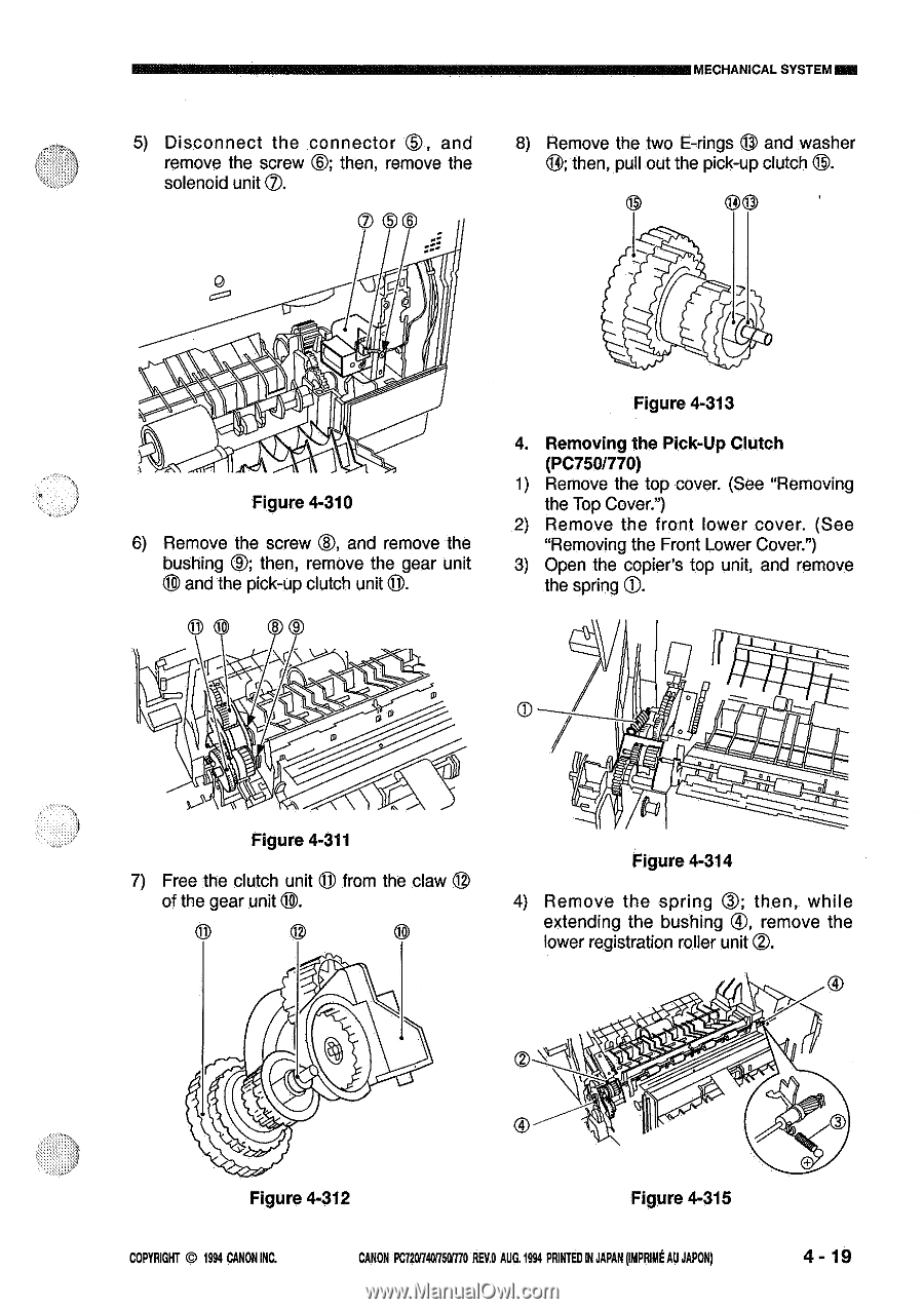
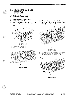
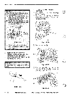
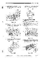
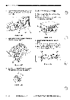
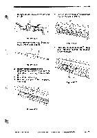
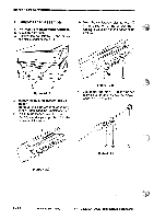
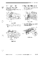
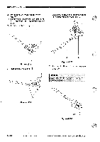
MECHANICAL SYSTEM NI2E ®, 5) Disconnect the connector and remove the screw e; then, remove the solenoid unit C). © S 8) Remove the two E-rings C) and washer ®; then, pull out the pick-up clutch 8. 00 ~QCO i1 Figure 4-310 ®, 6) Remove the screw and remove the bushing C); then, remove the gear unit 8 and the pick-up clutch unit 0. 11 8 9 „\c ." rrn Figure 4-313 4. Removing the Pick-Up Clutch (PC750/770) 1) Remove the top cover. (See "Removing the Top Cover.") 2) Remove the front lower cover. (See "Removing the Front Lower Cover.") 3) Open the copier's top unit, and remove the spring (D. Figure 4-311 7) Free the clutch unit ® from the claw of the gear unit t0. 0 0 ill Figure 4-314 4) Remove the spring C); then, while extending the bushing ®, remove the lower registration roller unit 0. O Figure 4-312 Figure 4-315 COPYRIGHT © 1994 CANON INC. CANON PC/20740750870 REV.O AUG.1994 PRINTEDIN JAPAN(gout AU JAPON) 4 - 19
-
 1
1 -
2
-
3
-
4
-
5
-
6
-
7
-
8
-
9
-
10
-
11
-
12
-
13
-
14
-
15
-
16
-
17
-
18
-
19
-
20
-
21
-
22
-
23
-
24
-
25
-
26
-
27
-
28
-
29
-
30
-
31
-
32
-
33
-
34
-
35
-
36
-
37
-
38
-
39
-
40
-
41
-
42
-
43
-
44
-
45
-
46
-
47
-
48
-
49
-
50
-
51
-
52
-
53
-
54
-
55
-
56
-
57
-
58
-
59
-
60
-
61
-
62
-
63
-
64
-
65
-
66
-
67
-
68
-
69
-
70
-
71
-
72
-
73
-
74
-
75
-
76
-
77
-
78
-
79
-
80
-
81
-
82
-
83
-
84
-
85
-
86
-
87
-
88
-
89
-
90
-
91
-
92
-
93
-
94
-
95
-
96
-
97
-
98
-
99
-
100
-
101
-
102
-
103
-
104
-
105
-
106
-
107
-
108
-
109
-
110
-
111
-
112
-
113
-
114
-
115
-
116
-
117
-
118
-
119
-
120
-
121
-
122
-
123
-
124
-
125
-
126
-
127
-
128
-
129
-
 130
130 -
 131
131 -
 132
132 -
 133
133 -
 134
134 -
 135
135 -
 136
136 -
 137
137 -
 138
138 -
 139
139 -
 140
140 -
141
-
142
-
143
-
144
-
145
-
146
-
147
-
148
-
149
-
150
-
151
-
152
-
153
-
154
-
155
-
156
-
157
-
158
-
159
-
160
-
161
-
162
-
163
-
164
-
165
-
166
-
167
-
168
-
169
-
170
-
171
-
172
-
173
-
174
-
175
-
176
-
177
-
178
-
179
-
180
-
181
-
182
-
183
-
184
-
185
-
186
-
187
-
188
-
189
-
190
-
191
-
192
-
193
-
194
-
195
-
196
-
197
-
198
-
199
-
200
 |
 |