Canon PC720 Service Manual - Page 53
Drive, System
 |
View all Canon PC720 manuals
Add to My Manuals
Save this manual to your list of manuals |
Page 53 highlights
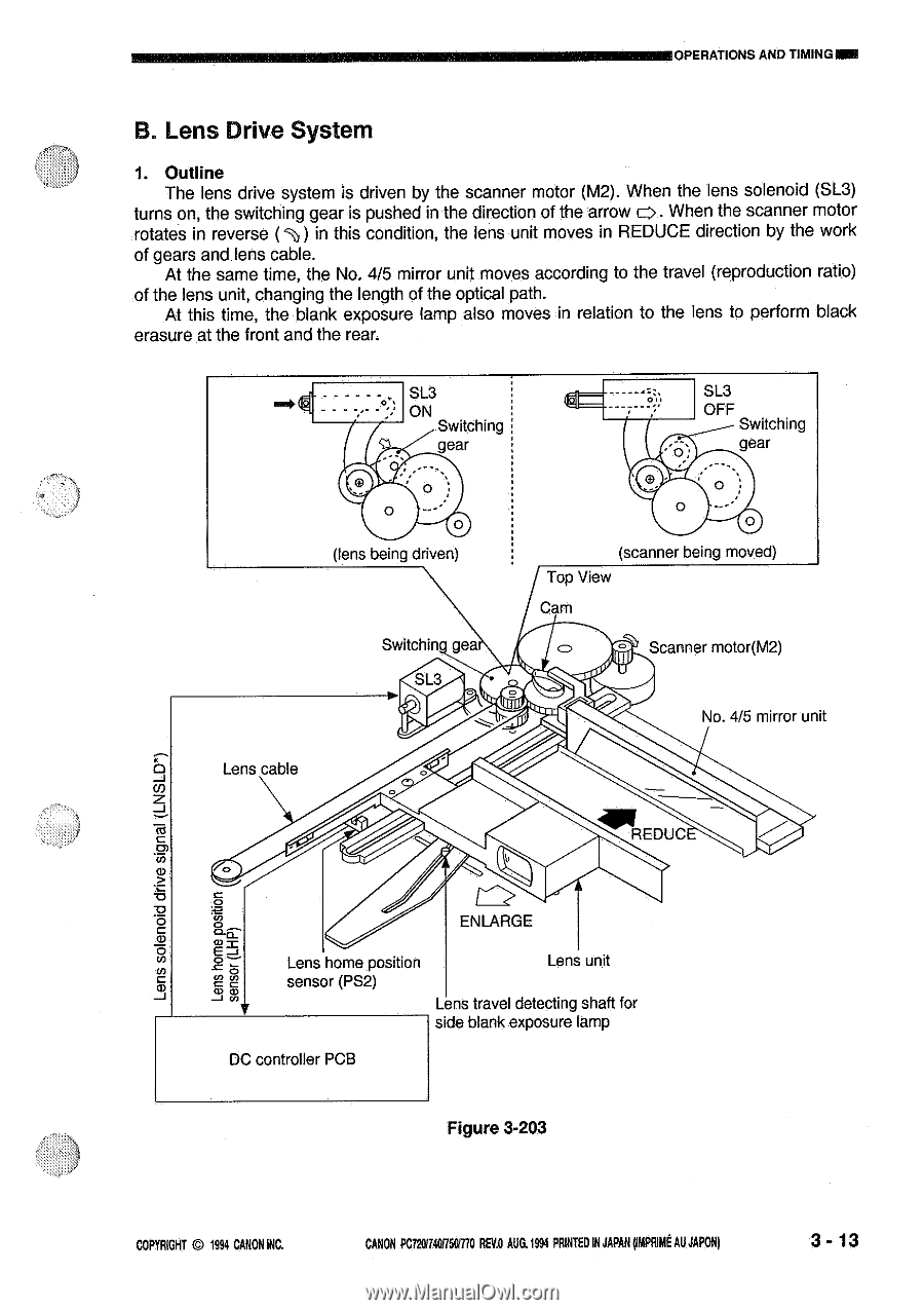
OPERATIONS AND TIMINGINN B. Lens Drive System 1. Outline The lens drive system is driven by the scanner motor (M2). When the lens solenoid (SL3) turns on, the switching gear is pushed in the direction of the arrow c>. When the scanner motor rotates in reverse ( 4%) in this condition, the lens unit moves in REDUCE direction by the work of gears and lens cable. At the same time, the No. 4/5 mirror unit moves according to the travel (reproduction ratio) of the lens unit, changing the length of the optical path. At this time, the blank exposure lamp also moves in relation to the lens to perform black erasure at the front and the rear. SL3 ON Switching gear SL3 OFF Switching gear 0 0 (lens being driven) Switchin. gea SL3 Lens cable 0 0 (scanner being moved) Top View Cam Scanner motor(M2) No. 4/5 mirror unit REDUC signal (LNSLD*) 0 :42 0 .= ,$) :0e CO CO J to ENLARGE Lens home position Lens unit sensor (PS2) Lens travel detecting shaft for side blank exposure lamp DC controller PCB Figure 3-203 COPYRIGHT © 1994 CANON INC. CANON PC7201740f750M0 AEU AUG.1994 PRINTED IN JAPAN (IMPRIME AU JAPAN) 3 - 13
-
 1
1 -
2
-
3
-
4
-
5
-
6
-
7
-
8
-
9
-
10
-
11
-
12
-
13
-
14
-
15
-
16
-
17
-
18
-
19
-
20
-
21
-
22
-
23
-
24
-
25
-
26
-
27
-
28
-
29
-
30
-
31
-
32
-
33
-
34
-
35
-
36
-
37
-
38
-
39
-
40
-
41
-
42
-
43
-
44
-
45
-
46
-
47
-
 48
48 -
 49
49 -
 50
50 -
 51
51 -
 52
52 -
 53
53 -
 54
54 -
 55
55 -
 56
56 -
 57
57 -
 58
58 -
59
-
60
-
61
-
62
-
63
-
64
-
65
-
66
-
67
-
68
-
69
-
70
-
71
-
72
-
73
-
74
-
75
-
76
-
77
-
78
-
79
-
80
-
81
-
82
-
83
-
84
-
85
-
86
-
87
-
88
-
89
-
90
-
91
-
92
-
93
-
94
-
95
-
96
-
97
-
98
-
99
-
100
-
101
-
102
-
103
-
104
-
105
-
106
-
107
-
108
-
109
-
110
-
111
-
112
-
113
-
114
-
115
-
116
-
117
-
118
-
119
-
120
-
121
-
122
-
123
-
124
-
125
-
126
-
127
-
128
-
129
-
130
-
131
-
132
-
133
-
134
-
135
-
136
-
137
-
138
-
139
-
140
-
141
-
142
-
143
-
144
-
145
-
146
-
147
-
148
-
149
-
150
-
151
-
152
-
153
-
154
-
155
-
156
-
157
-
158
-
159
-
160
-
161
-
162
-
163
-
164
-
165
-
166
-
167
-
168
-
169
-
170
-
171
-
172
-
173
-
174
-
175
-
176
-
177
-
178
-
179
-
180
-
181
-
182
-
183
-
184
-
185
-
186
-
187
-
188
-
189
-
190
-
191
-
192
-
193
-
194
-
195
-
196
-
197
-
198
-
199
-
200
 |
 |