Canon PC720 Service Manual - Page 68
Controlling, Transfer, Roller
 |
View all Canon PC720 manuals
Add to My Manuals
Save this manual to your list of manuals |
Page 68 highlights
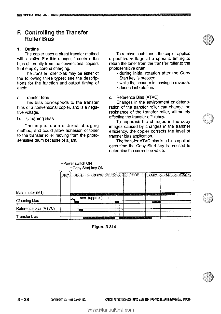
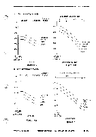
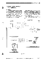
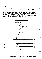
OPERATIONS AND TIMING F. Controlling the Transfer Roller Bias 1. Outline The copier uses a direct transfer method with a roller. For this reason, it controls the bias differently from the conventional copiers that employ corona charging. The transfer roller bias may be either of the following three types; see the descriptions for the function and output timing of each: a. Transfer Bias This bias corresponds to the transfer bias of a conventional copier, and is a negative voltage. b. Cleaning Bias The copier uses a direct charging method, and could allow adhesion of toner to the transfer roller moving from the photosensitive drum because of a jam. To remove such toner, the copier applies a positive voltage at a specific timing to return the toner from the transfer roller to the photosensitive drum. • during initial rotation after the Copy Start key is pressed. • while the scanner is moving in reverse. • during last rotation. c. Reference Bias (ATVC) Changes in the environment or deterio- ration of the transfer roller can change the resistance of the transfer roller, ultimately affecting the transfer efficiency. To suppress the changes in the copy images caused by changes in the transfer efficiency, the copier corrects the level of transfer bias application. The transfer ATVC bias is a bias applied each time the Copy Start key is pressed to determine the correction value. EPower switch ON I ECopy Start key ON 7 V STBY INTR SCFW SCRV SCFW SCRV 1STR STBY Main motor (M1) Cleaning bias Reference bias (ATVC) Transfer bias sec (approx.) U Figure 3-314 3 - 28 COPYRIGHT © 1994 CANON INC. CANON PC720/74000770 REV.O AUG.1994 PRINTED IN JAPAN pmpFeat AU JAPAN)
-
 1
1 -
2
-
3
-
4
-
5
-
6
-
7
-
8
-
9
-
10
-
11
-
12
-
13
-
14
-
15
-
16
-
17
-
18
-
19
-
20
-
21
-
22
-
23
-
24
-
25
-
26
-
27
-
28
-
29
-
30
-
31
-
32
-
33
-
34
-
35
-
36
-
37
-
38
-
39
-
40
-
41
-
42
-
43
-
44
-
45
-
46
-
47
-
48
-
49
-
50
-
51
-
52
-
53
-
54
-
55
-
56
-
57
-
58
-
59
-
60
-
61
-
62
-
 63
63 -
 64
64 -
 65
65 -
 66
66 -
 67
67 -
 68
68 -
 69
69 -
 70
70 -
 71
71 -
 72
72 -
 73
73 -
74
-
75
-
76
-
77
-
78
-
79
-
80
-
81
-
82
-
83
-
84
-
85
-
86
-
87
-
88
-
89
-
90
-
91
-
92
-
93
-
94
-
95
-
96
-
97
-
98
-
99
-
100
-
101
-
102
-
103
-
104
-
105
-
106
-
107
-
108
-
109
-
110
-
111
-
112
-
113
-
114
-
115
-
116
-
117
-
118
-
119
-
120
-
121
-
122
-
123
-
124
-
125
-
126
-
127
-
128
-
129
-
130
-
131
-
132
-
133
-
134
-
135
-
136
-
137
-
138
-
139
-
140
-
141
-
142
-
143
-
144
-
145
-
146
-
147
-
148
-
149
-
150
-
151
-
152
-
153
-
154
-
155
-
156
-
157
-
158
-
159
-
160
-
161
-
162
-
163
-
164
-
165
-
166
-
167
-
168
-
169
-
170
-
171
-
172
-
173
-
174
-
175
-
176
-
177
-
178
-
179
-
180
-
181
-
182
-
183
-
184
-
185
-
186
-
187
-
188
-
189
-
190
-
191
-
192
-
193
-
194
-
195
-
196
-
197
-
198
-
199
-
200
 |
 |