Canon PC720 Service Manual - Page 85
Fixing, Delivery
 |
View all Canon PC720 manuals
Add to My Manuals
Save this manual to your list of manuals |
Page 85 highlights
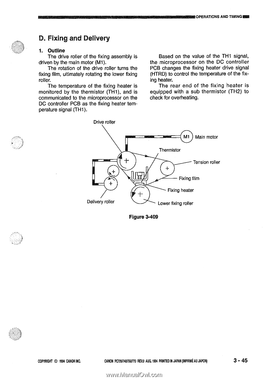
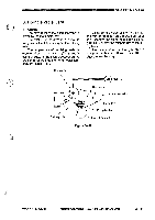
OPERATIONS AND TIMING D. Fixing and Delivery 1. Outline The drive roller of the fixing assembly is driven by the main motor (M1). The rotation of the drive roller turns the fixing film, ultimately rotating the lower fixing roller. The temperature of the fixing heater is monitored by the thermistor (TH1), and is communicated to the microprocessor on the DC controller PCB as the fixing heater temperature signal (TH1). Drive roller Based on the value of the TH1 signal, the microprocessor on the DC controller PCB changes the fixing heater drive signal (HTRD) to control the temperature of the fixing heater. The rear end of the fixing heater is equipped with a sub thermistor (TH2) to check for overheating. M1 Main motor Thermistor Tension roller Delivery roller Fixing film Fixing heater Lower fixing roller Figure 3-409 COPYRIGHT © 1994 CANON INC. CANON PC72017401750/170 REY.° AUG.1994 PRINTED IN JAPAN pmpRimt AU JAPON) 3-45
-
 1
1 -
2
-
3
-
4
-
5
-
6
-
7
-
8
-
9
-
10
-
11
-
12
-
13
-
14
-
15
-
16
-
17
-
18
-
19
-
20
-
21
-
22
-
23
-
24
-
25
-
26
-
27
-
28
-
29
-
30
-
31
-
32
-
33
-
34
-
35
-
36
-
37
-
38
-
39
-
40
-
41
-
42
-
43
-
44
-
45
-
46
-
47
-
48
-
49
-
50
-
51
-
52
-
53
-
54
-
55
-
56
-
57
-
58
-
59
-
60
-
61
-
62
-
63
-
64
-
65
-
66
-
67
-
68
-
69
-
70
-
71
-
72
-
73
-
74
-
75
-
76
-
77
-
78
-
79
-
 80
80 -
 81
81 -
 82
82 -
 83
83 -
 84
84 -
 85
85 -
 86
86 -
 87
87 -
 88
88 -
 89
89 -
 90
90 -
91
-
92
-
93
-
94
-
95
-
96
-
97
-
98
-
99
-
100
-
101
-
102
-
103
-
104
-
105
-
106
-
107
-
108
-
109
-
110
-
111
-
112
-
113
-
114
-
115
-
116
-
117
-
118
-
119
-
120
-
121
-
122
-
123
-
124
-
125
-
126
-
127
-
128
-
129
-
130
-
131
-
132
-
133
-
134
-
135
-
136
-
137
-
138
-
139
-
140
-
141
-
142
-
143
-
144
-
145
-
146
-
147
-
148
-
149
-
150
-
151
-
152
-
153
-
154
-
155
-
156
-
157
-
158
-
159
-
160
-
161
-
162
-
163
-
164
-
165
-
166
-
167
-
168
-
169
-
170
-
171
-
172
-
173
-
174
-
175
-
176
-
177
-
178
-
179
-
180
-
181
-
182
-
183
-
184
-
185
-
186
-
187
-
188
-
189
-
190
-
191
-
192
-
193
-
194
-
195
-
196
-
197
-
198
-
199
-
200
 |
 |