Canon PC720 Service Manual - Page 106
clockwise.
 |
View all Canon PC720 manuals
Add to My Manuals
Save this manual to your list of manuals |
Page 106 highlights
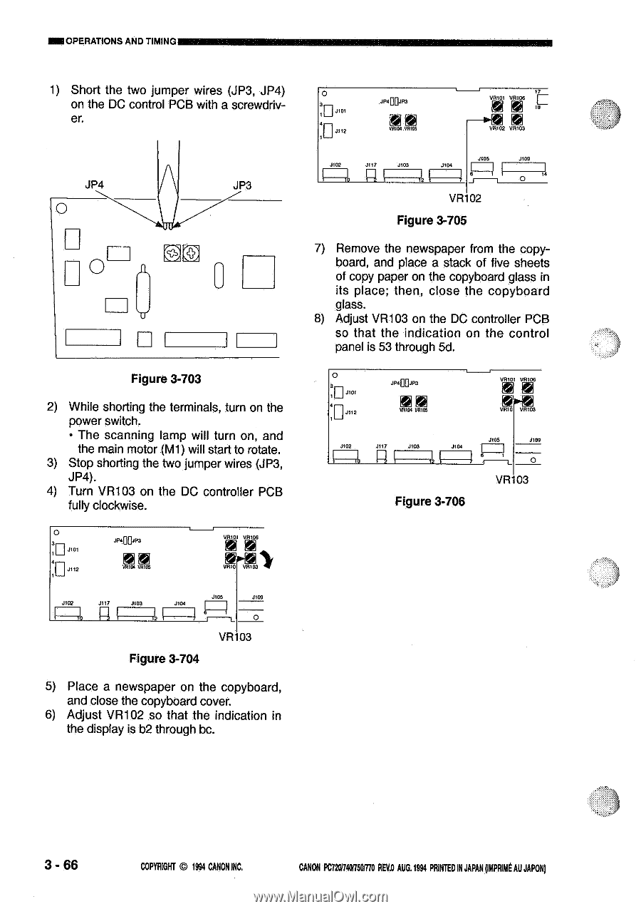
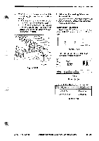
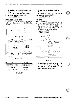
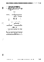
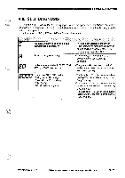
MNOPERATIONS AND TIMING 1) Short the two jumper wires (JP3, JP4) on the DC control PCB with a screwdriver. JP4 0 O JP3 U Figure 3-703 2) While shorting the terminals, turn on the power switch. • The scanning lamp will turn on, and the main motor (M1) will start to rotate. 3) Stop shorting the two jumper wires (JP3, JP4). 4) Turn VR103 on the DC controller PCB fully clockwise. 0 JP400.103 VA101 VR106 :0 VR104 0 11105 RIO J102 J117 .003 .1105 I±1 4 .1 11 0 VR 03 Figure 3-704 5) Place a newspaper on the copyboard, and close the copyboard cover. 6) Adjust VR102 so that the indication in the display is b2 through bc. o - .10100.1P3 VRIGI VR105 VA101 .108 t 18 VR102 V13103 ..1102 .1117 J105 1 1 J108 0 " VR 02 Figure 3-705 7) Remove the newspaper from the copyboard, and place a stack of five sheets of copy paper on the copyboard glass in its place; then, close the copyboard glass. 8) Adjust VR103 on the DC controller PCB so that the indication on the control panel is 53 through 5d. 0 1' 0 j1°' 113"2 .10400.103 VR104 1/B105 J402 J117 J1O3 J104 Figure 3-706 VA101 .106 J105 I .1109 0 VR 03 3-66 COPYRIGHT @ 1994 CANON INC. CANON PC72017401750/770 REVD AUG.1994 PRINTED IN JAPAN ompRimt AU JAPON)
-
 1
1 -
2
-
3
-
4
-
5
-
6
-
7
-
8
-
9
-
10
-
11
-
12
-
13
-
14
-
15
-
16
-
17
-
18
-
19
-
20
-
21
-
22
-
23
-
24
-
25
-
26
-
27
-
28
-
29
-
30
-
31
-
32
-
33
-
34
-
35
-
36
-
37
-
38
-
39
-
40
-
41
-
42
-
43
-
44
-
45
-
46
-
47
-
48
-
49
-
50
-
51
-
52
-
53
-
54
-
55
-
56
-
57
-
58
-
59
-
60
-
61
-
62
-
63
-
64
-
65
-
66
-
67
-
68
-
69
-
70
-
71
-
72
-
73
-
74
-
75
-
76
-
77
-
78
-
79
-
80
-
81
-
82
-
83
-
84
-
85
-
86
-
87
-
88
-
89
-
90
-
91
-
92
-
93
-
94
-
95
-
96
-
97
-
98
-
99
-
100
-
 101
101 -
 102
102 -
 103
103 -
 104
104 -
 105
105 -
 106
106 -
 107
107 -
 108
108 -
 109
109 -
 110
110 -
 111
111 -
112
-
113
-
114
-
115
-
116
-
117
-
118
-
119
-
120
-
121
-
122
-
123
-
124
-
125
-
126
-
127
-
128
-
129
-
130
-
131
-
132
-
133
-
134
-
135
-
136
-
137
-
138
-
139
-
140
-
141
-
142
-
143
-
144
-
145
-
146
-
147
-
148
-
149
-
150
-
151
-
152
-
153
-
154
-
155
-
156
-
157
-
158
-
159
-
160
-
161
-
162
-
163
-
164
-
165
-
166
-
167
-
168
-
169
-
170
-
171
-
172
-
173
-
174
-
175
-
176
-
177
-
178
-
179
-
180
-
181
-
182
-
183
-
184
-
185
-
186
-
187
-
188
-
189
-
190
-
191
-
192
-
193
-
194
-
195
-
196
-
197
-
198
-
199
-
200
 |
 |