Canon PC720 Service Manual - Page 124
FY9-3009-020
 |
View all Canon PC720 manuals
Add to My Manuals
Save this manual to your list of manuals |
Page 124 highlights
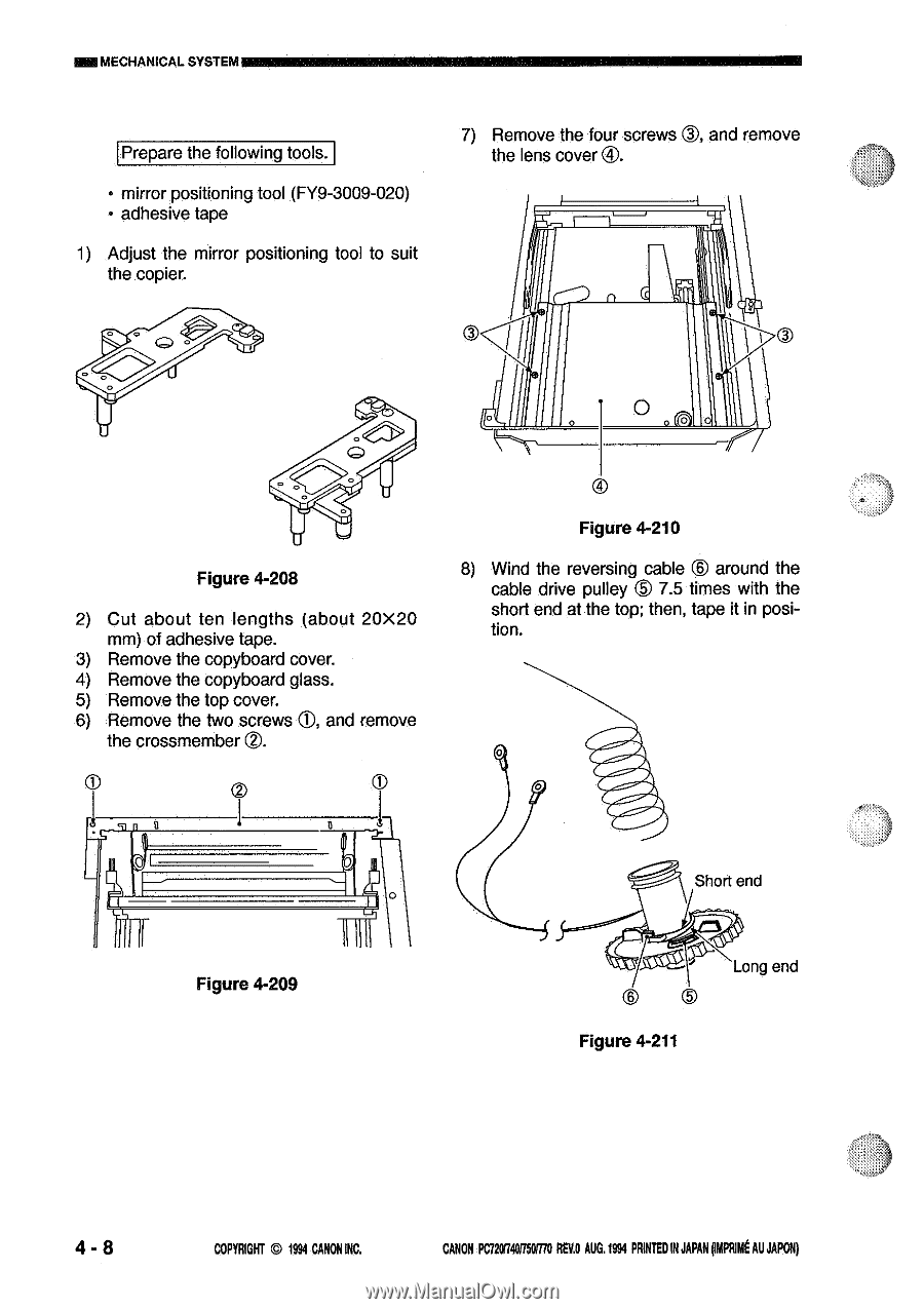
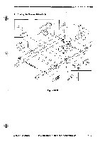
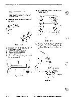
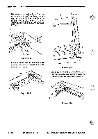
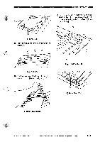
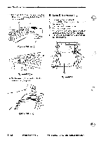
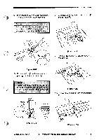
=I MECHANICAL SYSTEM Prepare the following tools. • mirror positioning tool (FY9-3009-020) • adhesive tape 1) Adjust the mirror positioning tool to suit the copier. 7) Remove the four screws CD, and remove the lens cover T. g 3 0 Figure 4-208 2) Cut about ten lengths (about 20X20 mm) of adhesive tape. 3) Remove the copyboard cover. 4) Remove the copyboard glass. 5) Remove the top cover. 6) Remove the two screws 0, and remove the crossmember O. 3 Figure 4-210 8) Wind the reversing cable ° around the cable drive pulley 0 7.5 times with the short end at the top; then, tape it in position. 0 it 1ll 11111 Figure 4-209 Short end ogV)- Long end 6 3 Figure 4-211 4 - 8 COPYRIGHT © 1994 CANON INC. CANON PC720I74011501/70 REV.0 AUG. 1994 PRINTED IN JAPAN pmpRimt AU JAPON)
-
 1
1 -
2
-
3
-
4
-
5
-
6
-
7
-
8
-
9
-
10
-
11
-
12
-
13
-
14
-
15
-
16
-
17
-
18
-
19
-
20
-
21
-
22
-
23
-
24
-
25
-
26
-
27
-
28
-
29
-
30
-
31
-
32
-
33
-
34
-
35
-
36
-
37
-
38
-
39
-
40
-
41
-
42
-
43
-
44
-
45
-
46
-
47
-
48
-
49
-
50
-
51
-
52
-
53
-
54
-
55
-
56
-
57
-
58
-
59
-
60
-
61
-
62
-
63
-
64
-
65
-
66
-
67
-
68
-
69
-
70
-
71
-
72
-
73
-
74
-
75
-
76
-
77
-
78
-
79
-
80
-
81
-
82
-
83
-
84
-
85
-
86
-
87
-
88
-
89
-
90
-
91
-
92
-
93
-
94
-
95
-
96
-
97
-
98
-
99
-
100
-
101
-
102
-
103
-
104
-
105
-
106
-
107
-
108
-
109
-
110
-
111
-
112
-
113
-
114
-
115
-
116
-
117
-
118
-
 119
119 -
 120
120 -
 121
121 -
 122
122 -
 123
123 -
 124
124 -
 125
125 -
 126
126 -
 127
127 -
 128
128 -
 129
129 -
130
-
131
-
132
-
133
-
134
-
135
-
136
-
137
-
138
-
139
-
140
-
141
-
142
-
143
-
144
-
145
-
146
-
147
-
148
-
149
-
150
-
151
-
152
-
153
-
154
-
155
-
156
-
157
-
158
-
159
-
160
-
161
-
162
-
163
-
164
-
165
-
166
-
167
-
168
-
169
-
170
-
171
-
172
-
173
-
174
-
175
-
176
-
177
-
178
-
179
-
180
-
181
-
182
-
183
-
184
-
185
-
186
-
187
-
188
-
189
-
190
-
191
-
192
-
193
-
194
-
195
-
196
-
197
-
198
-
199
-
200
 |
 |