Canon PC720 Service Manual - Page 35
Transfer
 |
View all Canon PC720 manuals
Add to My Manuals
Save this manual to your list of manuals |
Page 35 highlights
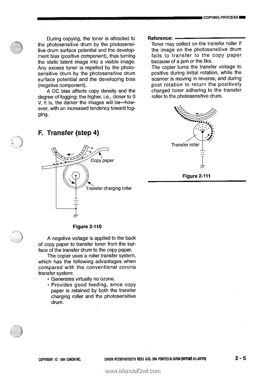
COPYING PROCESSIM During copying, the toner is attracted to the photosensitive drum by the photosensitive drum surface potential and the development bias (positive component), thus turning the static latent image into a visible image. Any excess toner is repelled by the photosensitive drum by the photosensitive drum surface potential and the developing bias (negative component). A DC bias affects copy density and the degree of fogging; the higher, i.e., closer to 0 V, it is, the darker the images will be-however, with an increased tendency toward fog- ging. Reference: Toner may collect on the transfer roller if the image on the photosensitive drum fails to transfer to the copy paper because of a jam or the like. The copier turns the transfer voltage to positive during initial rotation, while the scanner is moving in reverse, and during post rotation to return the positively charged toner adhering to the transfer roller to the photosensitive drum. F. Transfer (step 4) Copy paper Transfer charging roller 0 Transfer roller Figure 2-111 Figure 2-110 A negative voltage is applied to the back of copy paper to transfer toner from the surface of the transfer drum to the copy paper. The copier uses a roller transfer system, which has the following advantages when compared with the conventional corona transfer system: • Generates virtually no ozone. • Provides good feeding, since copy paper is retained by both the transfer charging roller and the photosensitive drum. COPYRIGHT 1994 CANON INC. CANON PC7201740/750,710 REV.0 AUG.1994 PRINTED IN JAPAN ompnimt AU JAPON) 2 - 5
-
 1
1 -
2
-
3
-
4
-
5
-
6
-
7
-
8
-
9
-
10
-
11
-
12
-
13
-
14
-
15
-
16
-
17
-
18
-
19
-
20
-
21
-
22
-
23
-
24
-
25
-
26
-
27
-
28
-
29
-
 30
30 -
 31
31 -
 32
32 -
 33
33 -
 34
34 -
 35
35 -
 36
36 -
 37
37 -
 38
38 -
 39
39 -
 40
40 -
41
-
42
-
43
-
44
-
45
-
46
-
47
-
48
-
49
-
50
-
51
-
52
-
53
-
54
-
55
-
56
-
57
-
58
-
59
-
60
-
61
-
62
-
63
-
64
-
65
-
66
-
67
-
68
-
69
-
70
-
71
-
72
-
73
-
74
-
75
-
76
-
77
-
78
-
79
-
80
-
81
-
82
-
83
-
84
-
85
-
86
-
87
-
88
-
89
-
90
-
91
-
92
-
93
-
94
-
95
-
96
-
97
-
98
-
99
-
100
-
101
-
102
-
103
-
104
-
105
-
106
-
107
-
108
-
109
-
110
-
111
-
112
-
113
-
114
-
115
-
116
-
117
-
118
-
119
-
120
-
121
-
122
-
123
-
124
-
125
-
126
-
127
-
128
-
129
-
130
-
131
-
132
-
133
-
134
-
135
-
136
-
137
-
138
-
139
-
140
-
141
-
142
-
143
-
144
-
145
-
146
-
147
-
148
-
149
-
150
-
151
-
152
-
153
-
154
-
155
-
156
-
157
-
158
-
159
-
160
-
161
-
162
-
163
-
164
-
165
-
166
-
167
-
168
-
169
-
170
-
171
-
172
-
173
-
174
-
175
-
176
-
177
-
178
-
179
-
180
-
181
-
182
-
183
-
184
-
185
-
186
-
187
-
188
-
189
-
190
-
191
-
192
-
193
-
194
-
195
-
196
-
197
-
198
-
199
-
200
 |
 |