Canon PC720 Service Manual - Page 54
Scanner, Drive, System
 |
View all Canon PC720 manuals
Add to My Manuals
Save this manual to your list of manuals |
Page 54 highlights
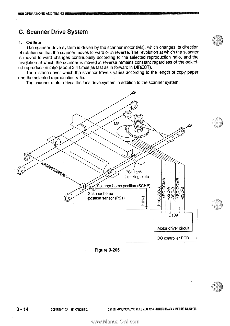
®OPERATIONS AND TIMING M lngEkkaSakt il C. Scanner Drive System 1. Outline The scanner drive system is driven by the scanner motor (M2), which changes its direction of rotation so that the scanner moves forward or in reverse. The revolution at which the scanner is moved forward changes continuously according to the selected reproduction ratio, and the revolution at which the scanner is moved in reverse remains constant regardless of the selected reproduction ratio (about 3.4 times as fast as in forward in DIRECT). The distance over which the scanner travels varies according to the length of copy paper and the selected reproduction ratio. The scanner motor drives the lens drive system in addition to the scanner system. M2 PSI lightblocking plate Scanner home position (SCHP) Scanner home position sensor (PSI) O 2 O O c9 O co (ID rn rn rn O Q1O9 Figure 3-205 Motor driver circuit DC controller PCB 3 - 14 COPYRIGHT © 1994 CANON INC. CANON PC729R4017501170 REV.O AUG. 1994 PRINTED IN JAPAN (IMPRIME AU JAPON)
-
 1
1 -
2
-
3
-
4
-
5
-
6
-
7
-
8
-
9
-
10
-
11
-
12
-
13
-
14
-
15
-
16
-
17
-
18
-
19
-
20
-
21
-
22
-
23
-
24
-
25
-
26
-
27
-
28
-
29
-
30
-
31
-
32
-
33
-
34
-
35
-
36
-
37
-
38
-
39
-
40
-
41
-
42
-
43
-
44
-
45
-
46
-
47
-
48
-
 49
49 -
 50
50 -
 51
51 -
 52
52 -
 53
53 -
 54
54 -
 55
55 -
 56
56 -
 57
57 -
 58
58 -
 59
59 -
60
-
61
-
62
-
63
-
64
-
65
-
66
-
67
-
68
-
69
-
70
-
71
-
72
-
73
-
74
-
75
-
76
-
77
-
78
-
79
-
80
-
81
-
82
-
83
-
84
-
85
-
86
-
87
-
88
-
89
-
90
-
91
-
92
-
93
-
94
-
95
-
96
-
97
-
98
-
99
-
100
-
101
-
102
-
103
-
104
-
105
-
106
-
107
-
108
-
109
-
110
-
111
-
112
-
113
-
114
-
115
-
116
-
117
-
118
-
119
-
120
-
121
-
122
-
123
-
124
-
125
-
126
-
127
-
128
-
129
-
130
-
131
-
132
-
133
-
134
-
135
-
136
-
137
-
138
-
139
-
140
-
141
-
142
-
143
-
144
-
145
-
146
-
147
-
148
-
149
-
150
-
151
-
152
-
153
-
154
-
155
-
156
-
157
-
158
-
159
-
160
-
161
-
162
-
163
-
164
-
165
-
166
-
167
-
168
-
169
-
170
-
171
-
172
-
173
-
174
-
175
-
176
-
177
-
178
-
179
-
180
-
181
-
182
-
183
-
184
-
185
-
186
-
187
-
188
-
189
-
190
-
191
-
192
-
193
-
194
-
195
-
196
-
197
-
198
-
199
-
200
 |
 |