Canon PC720 Service Manual - Page 64
Controlling, Developing, Separation, Static, Eliminator
 |
View all Canon PC720 manuals
Add to My Manuals
Save this manual to your list of manuals |
Page 64 highlights
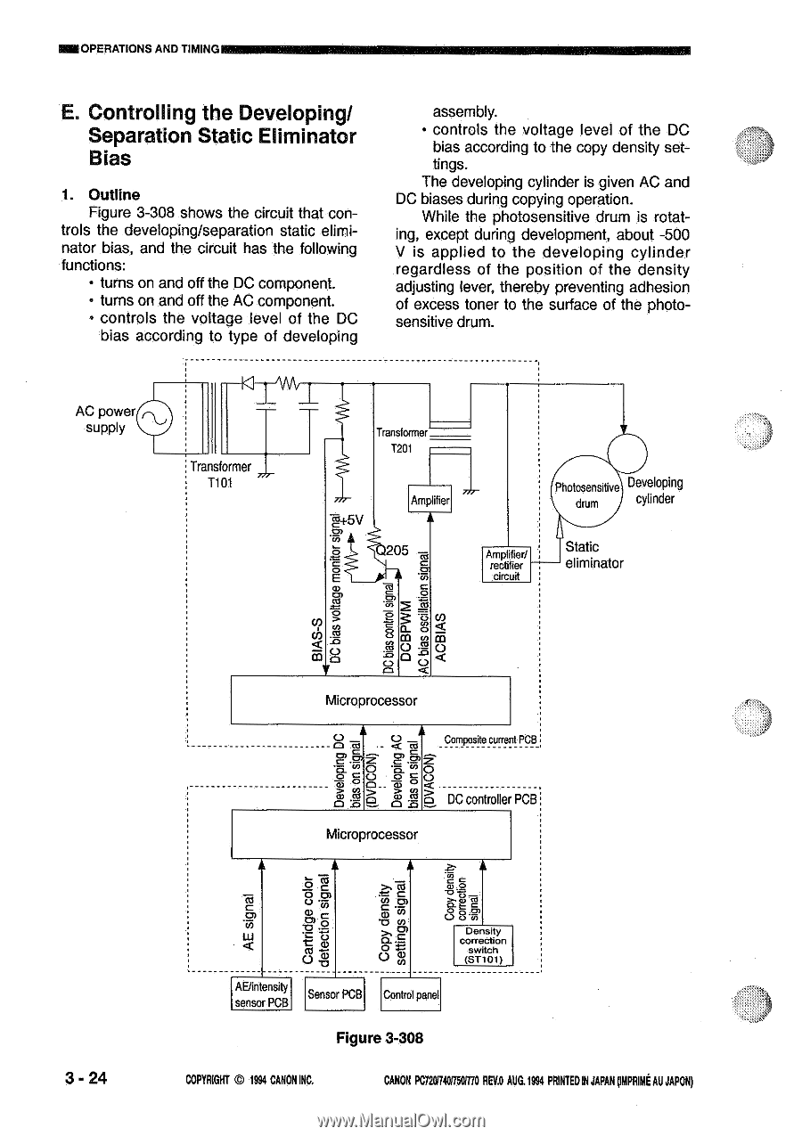
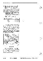
ME OPERATIONS AND TIMING E. Controlling the Developing/ Separation Static Eliminator Bias 1. Outline Figure 3-308 shows the circuit that con- trols the developing/separation static eliminator bias, and the circuit has the following functions: • turns on and off the DC component. • turns on and off the AC component. • controls the voltage level of the DC bias according to type of developing assembly. • controls the voltage level of the DC bias according to the copy density settings. The developing cylinder is given AC and DC biases during copying operation. While the photosensitive drum is rotating, except during development, about -500 V is applied to the developing cylinder regardless of the position of the density adjusting lever, thereby preventing adhesion of excess toner to the surface of the photosensitive drum. AC power supply 1 Transformer T101 Transformer T2O1 1=.4 5V Amplifier 205 -ea rn r9i) Ea Photosensitive Developing drum cylinder Ampl fier/ rect fier - circuit Static eliminator 3 - 24 Microprocessor Oc utt < Composite current PCB o OV 7=C.0D O - RS 25 CI 0 o a> ) O o tu 25 O DC controller PCB Microprocessor o Co oo 0) a) C w 0) :FEO- o O • TcDD.O al at 8 8 Density correction swlch (ST101) AE/intensity senso PCB Senso PCB Control panel Figure 3-308 COPYRIGHT © 1994 CANON INC. CANON PC72074017501710 REIM AUG.1994 PRINTED IN JAPAN omPFumt AU JAPONI
-
 1
1 -
2
-
3
-
4
-
5
-
6
-
7
-
8
-
9
-
10
-
11
-
12
-
13
-
14
-
15
-
16
-
17
-
18
-
19
-
20
-
21
-
22
-
23
-
24
-
25
-
26
-
27
-
28
-
29
-
30
-
31
-
32
-
33
-
34
-
35
-
36
-
37
-
38
-
39
-
40
-
41
-
42
-
43
-
44
-
45
-
46
-
47
-
48
-
49
-
50
-
51
-
52
-
53
-
54
-
55
-
56
-
57
-
58
-
 59
59 -
 60
60 -
 61
61 -
 62
62 -
 63
63 -
 64
64 -
 65
65 -
 66
66 -
 67
67 -
 68
68 -
 69
69 -
70
-
71
-
72
-
73
-
74
-
75
-
76
-
77
-
78
-
79
-
80
-
81
-
82
-
83
-
84
-
85
-
86
-
87
-
88
-
89
-
90
-
91
-
92
-
93
-
94
-
95
-
96
-
97
-
98
-
99
-
100
-
101
-
102
-
103
-
104
-
105
-
106
-
107
-
108
-
109
-
110
-
111
-
112
-
113
-
114
-
115
-
116
-
117
-
118
-
119
-
120
-
121
-
122
-
123
-
124
-
125
-
126
-
127
-
128
-
129
-
130
-
131
-
132
-
133
-
134
-
135
-
136
-
137
-
138
-
139
-
140
-
141
-
142
-
143
-
144
-
145
-
146
-
147
-
148
-
149
-
150
-
151
-
152
-
153
-
154
-
155
-
156
-
157
-
158
-
159
-
160
-
161
-
162
-
163
-
164
-
165
-
166
-
167
-
168
-
169
-
170
-
171
-
172
-
173
-
174
-
175
-
176
-
177
-
178
-
179
-
180
-
181
-
182
-
183
-
184
-
185
-
186
-
187
-
188
-
189
-
190
-
191
-
192
-
193
-
194
-
195
-
196
-
197
-
198
-
199
-
200
 |
 |