Canon PC720 Service Manual - Page 81
leading edge
 |
View all Canon PC720 manuals
Add to My Manuals
Save this manual to your list of manuals |
Page 81 highlights
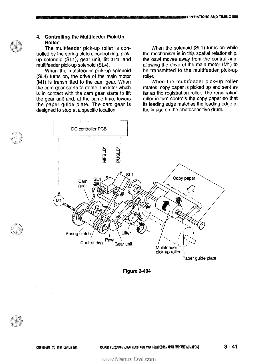
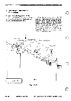
UOPERATIONS AND TIMINGFA 4. Controlling the Multifeeder Pick-Up Roller The multifeeder pick-up roller is con- trolled by the spring clutch, control ring, pickup solenoid (SL1), gear unit, lift arm, and multifeeder pick-up solenoid (SL4). When the multifeeder pick-up solenoid (SL4) turns on, the drive of the main motor (M1) is transmitted to the cam gear. When the cam gear starts to rotate, the lifter which is in contact with the cam gear starts to lift the gear unit and, at the same time, lowers the paper guide plate. The cam gear is designed to stop at a specific location. When the solenoid (SL1) turns on while the mechanism is in this spatial relationship, the pawl moves away from the control ring, allowing the drive of the main motor (M1) to be transmitted to the multifeeder pick-up roller. When the multifeeder pick-up roller rotates, copy paper is picked up and sent as far as the registration roller. The registration roller in turn controls the copy paper so that its leading edge matches the leading edge of the image on the photosensitive drum. DC controller PCB rLnL 2 SL1 Cam SL4 gear *TP MI Copy paper Spring clutch Lifter Control ring Pawl Gear unit Multifeeder pick-up roller Paper guide plate Figure 3-404 COPYRIGHT © 1994 CANON INC. CANON PC120.740750i7i0 REV.O AUG.1994 PRINTED INJAPAN ompRimt AUJAPON) 3 - 41
-
 1
1 -
2
-
3
-
4
-
5
-
6
-
7
-
8
-
9
-
10
-
11
-
12
-
13
-
14
-
15
-
16
-
17
-
18
-
19
-
20
-
21
-
22
-
23
-
24
-
25
-
26
-
27
-
28
-
29
-
30
-
31
-
32
-
33
-
34
-
35
-
36
-
37
-
38
-
39
-
40
-
41
-
42
-
43
-
44
-
45
-
46
-
47
-
48
-
49
-
50
-
51
-
52
-
53
-
54
-
55
-
56
-
57
-
58
-
59
-
60
-
61
-
62
-
63
-
64
-
65
-
66
-
67
-
68
-
69
-
70
-
71
-
72
-
73
-
74
-
75
-
 76
76 -
 77
77 -
 78
78 -
 79
79 -
 80
80 -
 81
81 -
 82
82 -
 83
83 -
 84
84 -
 85
85 -
 86
86 -
87
-
88
-
89
-
90
-
91
-
92
-
93
-
94
-
95
-
96
-
97
-
98
-
99
-
100
-
101
-
102
-
103
-
104
-
105
-
106
-
107
-
108
-
109
-
110
-
111
-
112
-
113
-
114
-
115
-
116
-
117
-
118
-
119
-
120
-
121
-
122
-
123
-
124
-
125
-
126
-
127
-
128
-
129
-
130
-
131
-
132
-
133
-
134
-
135
-
136
-
137
-
138
-
139
-
140
-
141
-
142
-
143
-
144
-
145
-
146
-
147
-
148
-
149
-
150
-
151
-
152
-
153
-
154
-
155
-
156
-
157
-
158
-
159
-
160
-
161
-
162
-
163
-
164
-
165
-
166
-
167
-
168
-
169
-
170
-
171
-
172
-
173
-
174
-
175
-
176
-
177
-
178
-
179
-
180
-
181
-
182
-
183
-
184
-
185
-
186
-
187
-
188
-
189
-
190
-
191
-
192
-
193
-
194
-
195
-
196
-
197
-
198
-
199
-
200
 |
 |