Canon PC720 Service Manual - Page 147
Disconnect, connector, connectors, troller, Remove, screw, remove, upper, fixing, plate,
 |
View all Canon PC720 manuals
Add to My Manuals
Save this manual to your list of manuals |
Page 147 highlights
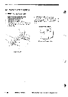
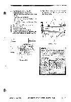
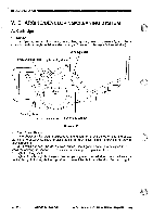
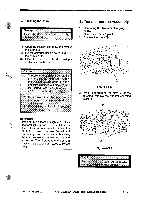
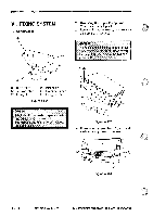
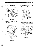
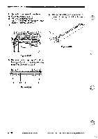
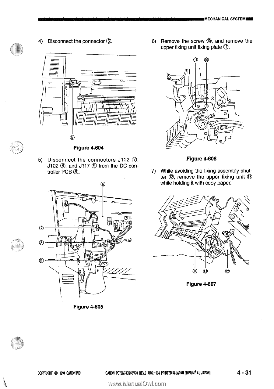
®. 4) Disconnect the connector MECHANICAL SYSTEMME 6) Remove the screw 8, and remove the upper fixing unit fixing plate 0. CD ?1).1;\\\1\\I x 0 Figure 4-604 5) Disconnect the connectors J112 0, ®, J102 and J117 ® from the DC con- troller PCB ®. Figure 4-606 7) While avoiding the fixing assembly shutter ©, remove the upper fixing unit 0 while holding it with copy paper. UG3G Figure 4-605 0 Figure 4-607 COPYRIGHT © 1994 CANON INC. CANON PC72017401750R70 REV.0 AUG.1994 PRINTED IN JAPAN ompRitit AU JAPON) 4 - 31
-
 1
1 -
2
-
3
-
4
-
5
-
6
-
7
-
8
-
9
-
10
-
11
-
12
-
13
-
14
-
15
-
16
-
17
-
18
-
19
-
20
-
21
-
22
-
23
-
24
-
25
-
26
-
27
-
28
-
29
-
30
-
31
-
32
-
33
-
34
-
35
-
36
-
37
-
38
-
39
-
40
-
41
-
42
-
43
-
44
-
45
-
46
-
47
-
48
-
49
-
50
-
51
-
52
-
53
-
54
-
55
-
56
-
57
-
58
-
59
-
60
-
61
-
62
-
63
-
64
-
65
-
66
-
67
-
68
-
69
-
70
-
71
-
72
-
73
-
74
-
75
-
76
-
77
-
78
-
79
-
80
-
81
-
82
-
83
-
84
-
85
-
86
-
87
-
88
-
89
-
90
-
91
-
92
-
93
-
94
-
95
-
96
-
97
-
98
-
99
-
100
-
101
-
102
-
103
-
104
-
105
-
106
-
107
-
108
-
109
-
110
-
111
-
112
-
113
-
114
-
115
-
116
-
117
-
118
-
119
-
120
-
121
-
122
-
123
-
124
-
125
-
126
-
127
-
128
-
129
-
130
-
131
-
132
-
133
-
134
-
135
-
136
-
137
-
138
-
139
-
140
-
141
-
 142
142 -
 143
143 -
 144
144 -
 145
145 -
 146
146 -
 147
147 -
 148
148 -
 149
149 -
 150
150 -
 151
151 -
 152
152 -
153
-
154
-
155
-
156
-
157
-
158
-
159
-
160
-
161
-
162
-
163
-
164
-
165
-
166
-
167
-
168
-
169
-
170
-
171
-
172
-
173
-
174
-
175
-
176
-
177
-
178
-
179
-
180
-
181
-
182
-
183
-
184
-
185
-
186
-
187
-
188
-
189
-
190
-
191
-
192
-
193
-
194
-
195
-
196
-
197
-
198
-
199
-
200
 |
 |
MECHANICAL
SYSTEM
ME
4)
Disconnect
the
connector
®.
?1).
1;\\\1\\I
Figure
4-604
5)
Disconnect
the
connectors
J112
0,
J102
®,
and
J117
®
from
the
DC
con-
troller
PCB
®.
Figure
4-605
UG3G
6)
Remove
the
screw
8,
and
remove
the
upper
fixing
unit
fixing
plate
0.
0
CD
x
Figure
4-606
7)
While
avoiding
the
fixing
assembly
shut-
ter
©,
remove
the
upper
fixing
unit
0
while
holding
it
with
copy
paper.
0
Figure
4-607
COPYRIGHT
©
1994
CANON
INC.
CANON
PC72017401750R70
REV.0
AUG.1994
PRINTED
IN
JAPAN
ompRitit
AU
JAPON)
4
-
31