Canon PC720 Service Manual - Page 66
density correction
 |
View all Canon PC720 manuals
Add to My Manuals
Save this manual to your list of manuals |
Page 66 highlights
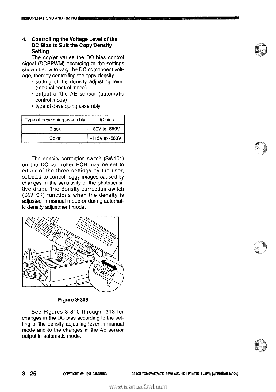
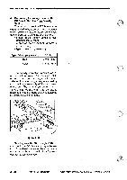
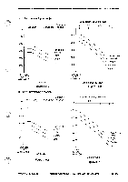
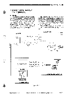
MEIOPERATIONS AND TIMING ,,,,,w,:m.k- ;,.onw44.0.. 4. Controlling the Voltage Level of the DC Bias to Suit the Copy Density Setting The copier varies the DC bias control signal (DCBPWM) according to the settings shown below to vary the DC component voltage, thereby controlling the copy density. • setting of the density adjusting lever (manual control mode) • output of the AE sensor (automatic control mode) • type of developing assembly Type of developing assembly DC bias Black -80V to -550V Color -115V to -580V The density correction switch (SW101) on the DC controller PCB may be set to either of the three settings by the user, selected to correct foggy images caused by changes in the sensitivity of the photosensitive drum. The density correction switch (SW101) functions when the density is adjusted in manual mode or during automatic density adjustment mode. 0 .miera cts 'qA Figure 3-309 See Figures 3-310 through -313 for changes in the DC bias according to the setting of the density adjusting lever in manual mode and to the changes in the AE sensor output in automatic mode. 3 - 26 COPYRIGHT @ 1994 CANON INC. CANON PC72017401750/770 REV.O AUG.19M PRINTEDIN JAPAN pout AU JAPON)
-
 1
1 -
2
-
3
-
4
-
5
-
6
-
7
-
8
-
9
-
10
-
11
-
12
-
13
-
14
-
15
-
16
-
17
-
18
-
19
-
20
-
21
-
22
-
23
-
24
-
25
-
26
-
27
-
28
-
29
-
30
-
31
-
32
-
33
-
34
-
35
-
36
-
37
-
38
-
39
-
40
-
41
-
42
-
43
-
44
-
45
-
46
-
47
-
48
-
49
-
50
-
51
-
52
-
53
-
54
-
55
-
56
-
57
-
58
-
59
-
60
-
 61
61 -
 62
62 -
 63
63 -
 64
64 -
 65
65 -
 66
66 -
 67
67 -
 68
68 -
 69
69 -
 70
70 -
 71
71 -
72
-
73
-
74
-
75
-
76
-
77
-
78
-
79
-
80
-
81
-
82
-
83
-
84
-
85
-
86
-
87
-
88
-
89
-
90
-
91
-
92
-
93
-
94
-
95
-
96
-
97
-
98
-
99
-
100
-
101
-
102
-
103
-
104
-
105
-
106
-
107
-
108
-
109
-
110
-
111
-
112
-
113
-
114
-
115
-
116
-
117
-
118
-
119
-
120
-
121
-
122
-
123
-
124
-
125
-
126
-
127
-
128
-
129
-
130
-
131
-
132
-
133
-
134
-
135
-
136
-
137
-
138
-
139
-
140
-
141
-
142
-
143
-
144
-
145
-
146
-
147
-
148
-
149
-
150
-
151
-
152
-
153
-
154
-
155
-
156
-
157
-
158
-
159
-
160
-
161
-
162
-
163
-
164
-
165
-
166
-
167
-
168
-
169
-
170
-
171
-
172
-
173
-
174
-
175
-
176
-
177
-
178
-
179
-
180
-
181
-
182
-
183
-
184
-
185
-
186
-
187
-
188
-
189
-
190
-
191
-
192
-
193
-
194
-
195
-
196
-
197
-
198
-
199
-
200
 |
 |