Canon PC720 Service Manual - Page 69
Microprocessor
 |
View all Canon PC720 manuals
Add to My Manuals
Save this manual to your list of manuals |
Page 69 highlights
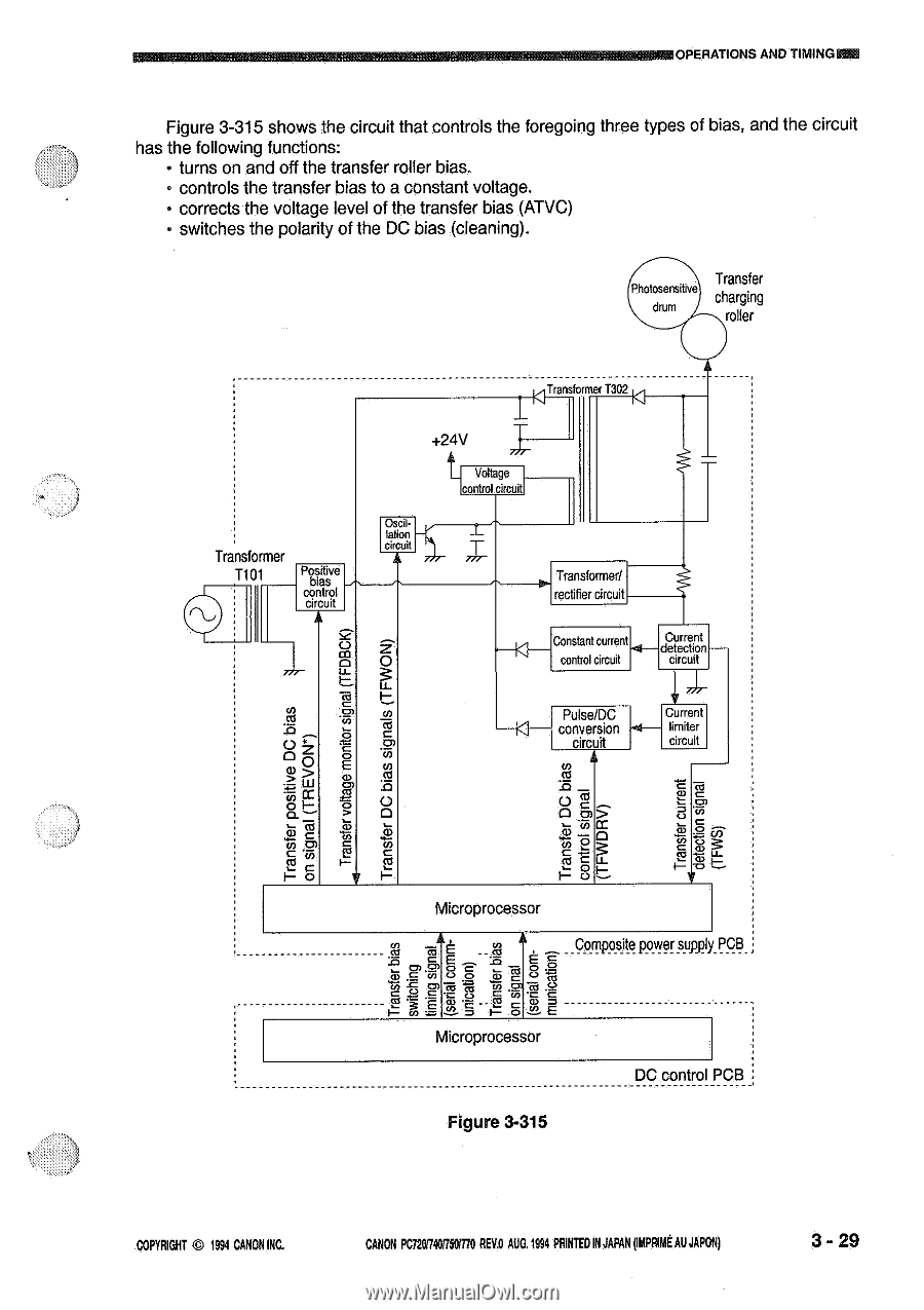
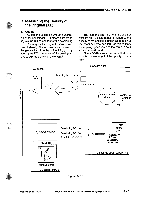
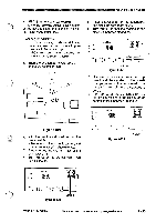
I OPERATIONS AND TIMING Figure 3-315 shows the circuit that controls the foregoing three types of bias, and the circuit has the following functions: • turns on and off the transfer roller bias. • controls the transfer bias to a constant voltage. • corrects the voltage level of the transfer bias (ATVC) - switches the polarity of the DC bias (cleaning). Transfer Photosensitive charging drum roller former 1302 +24V tl Voltage77-/control circuit Trans ormer T 0 Positive bias control circuit A 0 ciliation circuit 0 Transformer/ rectifier circuit Constant current control circuit Current detection - circuit Ca Io-n "c7r er DC bias sian .6"" C.) O >0 w 0 IC-C o0n1 0. (15 uc ) C EIL c 1- 0 I- Pulse/DC cone sion circuit o or >cc u) 2 -(S C Microprocessor Current limiter circuit a Composite power supply PCB U 0 0 -2 Oo "1-7, O E 1P-2 C0..00.1,.E Microprocessor DC control PCB Figure 3-315 COPYRIGHT © 1994 CANONINC. CANON PC72017401T50/770 REV.0 AUG.1994 PRINTED IN JAPAN (IMPRIME AU JAPON) 3 - 29
-
 1
1 -
2
-
3
-
4
-
5
-
6
-
7
-
8
-
9
-
10
-
11
-
12
-
13
-
14
-
15
-
16
-
17
-
18
-
19
-
20
-
21
-
22
-
23
-
24
-
25
-
26
-
27
-
28
-
29
-
30
-
31
-
32
-
33
-
34
-
35
-
36
-
37
-
38
-
39
-
40
-
41
-
42
-
43
-
44
-
45
-
46
-
47
-
48
-
49
-
50
-
51
-
52
-
53
-
54
-
55
-
56
-
57
-
58
-
59
-
60
-
61
-
62
-
63
-
 64
64 -
 65
65 -
 66
66 -
 67
67 -
 68
68 -
 69
69 -
 70
70 -
 71
71 -
 72
72 -
 73
73 -
 74
74 -
75
-
76
-
77
-
78
-
79
-
80
-
81
-
82
-
83
-
84
-
85
-
86
-
87
-
88
-
89
-
90
-
91
-
92
-
93
-
94
-
95
-
96
-
97
-
98
-
99
-
100
-
101
-
102
-
103
-
104
-
105
-
106
-
107
-
108
-
109
-
110
-
111
-
112
-
113
-
114
-
115
-
116
-
117
-
118
-
119
-
120
-
121
-
122
-
123
-
124
-
125
-
126
-
127
-
128
-
129
-
130
-
131
-
132
-
133
-
134
-
135
-
136
-
137
-
138
-
139
-
140
-
141
-
142
-
143
-
144
-
145
-
146
-
147
-
148
-
149
-
150
-
151
-
152
-
153
-
154
-
155
-
156
-
157
-
158
-
159
-
160
-
161
-
162
-
163
-
164
-
165
-
166
-
167
-
168
-
169
-
170
-
171
-
172
-
173
-
174
-
175
-
176
-
177
-
178
-
179
-
180
-
181
-
182
-
183
-
184
-
185
-
186
-
187
-
188
-
189
-
190
-
191
-
192
-
193
-
194
-
195
-
196
-
197
-
198
-
199
-
200
 |
 |