Canon PC720 Service Manual - Page 78
Controlling, Roller
 |
View all Canon PC720 manuals
Add to My Manuals
Save this manual to your list of manuals |
Page 78 highlights
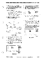
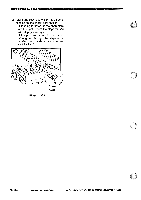
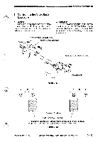
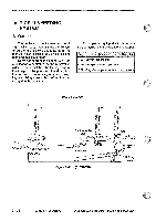
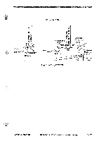
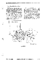
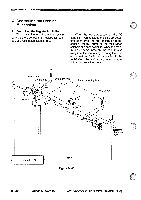
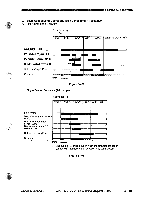
NMOPERATIONS AND TIMINGIll imuie B. Controlling the Pick-Up Roller 1. Outline The construction of the copier's pick-up roller differs depending on the model. The PC720/740's pick-up roller consists of a cassette pick-up roller and a singlefeeder pick-up roller. The cassette pick-up roller starts to rotate as soon as the pick-up solenoid turns on while the main motor is rotating. The single feeder pick-up roller rotates whenever the main motor is rotating. The PC750/770's pick-up roller consists of a cassette pick-up roller and a multifeeder pick-up roller. The drive to these pick-up rollers is switched by the gear unit, which changes the route of drive transmission; this way, the drive is transmitted to either of the two at a time. 2. Controlling the Cassette Pick-Up Roller The cassette pick-up roller is controlled by the spring clutch, control ring, and pick-up solenoid (SL1). When the solenoid turns on, the pawl moves away from the control ring, thereby allowing the drive of the main motor (M1) to be transmitted to the pick-up roller. When the pick-up roller starts to rotate, copy paper is picked up and sent as far as the registration roller. The registration roller, in turn, serves to control the copy paper so that it matches the leading edge of the image on the photosensitive drum. 3 - 38 COPYRIGHT © 1994 CANON INC. CANON PC72O740(750!T70 REV.O AUG.1994 PRINTED IN JAPAN EMPRIME AU JAPON)
-
 1
1 -
2
-
3
-
4
-
5
-
6
-
7
-
8
-
9
-
10
-
11
-
12
-
13
-
14
-
15
-
16
-
17
-
18
-
19
-
20
-
21
-
22
-
23
-
24
-
25
-
26
-
27
-
28
-
29
-
30
-
31
-
32
-
33
-
34
-
35
-
36
-
37
-
38
-
39
-
40
-
41
-
42
-
43
-
44
-
45
-
46
-
47
-
48
-
49
-
50
-
51
-
52
-
53
-
54
-
55
-
56
-
57
-
58
-
59
-
60
-
61
-
62
-
63
-
64
-
65
-
66
-
67
-
68
-
69
-
70
-
71
-
72
-
 73
73 -
 74
74 -
 75
75 -
 76
76 -
 77
77 -
 78
78 -
 79
79 -
 80
80 -
 81
81 -
 82
82 -
 83
83 -
84
-
85
-
86
-
87
-
88
-
89
-
90
-
91
-
92
-
93
-
94
-
95
-
96
-
97
-
98
-
99
-
100
-
101
-
102
-
103
-
104
-
105
-
106
-
107
-
108
-
109
-
110
-
111
-
112
-
113
-
114
-
115
-
116
-
117
-
118
-
119
-
120
-
121
-
122
-
123
-
124
-
125
-
126
-
127
-
128
-
129
-
130
-
131
-
132
-
133
-
134
-
135
-
136
-
137
-
138
-
139
-
140
-
141
-
142
-
143
-
144
-
145
-
146
-
147
-
148
-
149
-
150
-
151
-
152
-
153
-
154
-
155
-
156
-
157
-
158
-
159
-
160
-
161
-
162
-
163
-
164
-
165
-
166
-
167
-
168
-
169
-
170
-
171
-
172
-
173
-
174
-
175
-
176
-
177
-
178
-
179
-
180
-
181
-
182
-
183
-
184
-
185
-
186
-
187
-
188
-
189
-
190
-
191
-
192
-
193
-
194
-
195
-
196
-
197
-
198
-
199
-
200
 |
 |