Canon PC720 Service Manual - Page 128
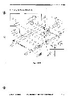
Drive, Assembly
 |
View all Canon PC720 manuals
Add to My Manuals
Save this manual to your list of manuals |
Page 128 highlights
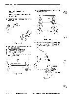
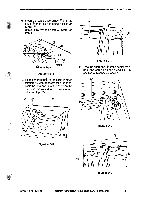
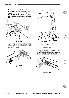
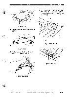
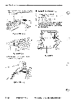
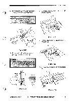
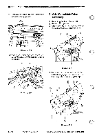
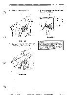
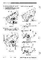
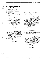
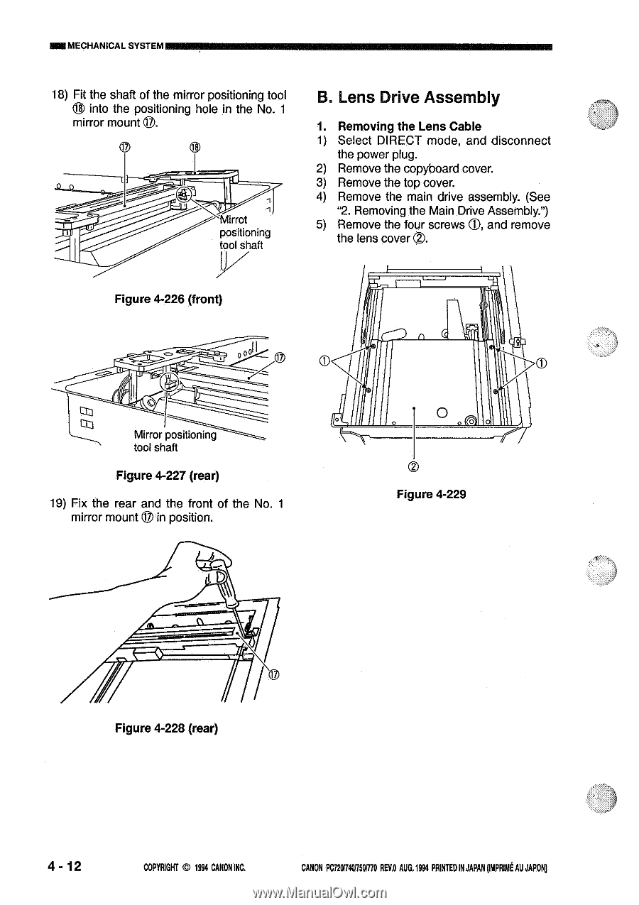
- MECHANICAL SYSTEM 18) Fit the shaft of the mirror positioning tool into the positioning hole in the No. 1 mirror mount 0. 8 Q 18 .Mirrot positioning tool shaft B. Lens Drive Assembly 1. Removing the Lens Cable 1) Select DIRECT mode, and disconnect the power plug. 2) Remove the copyboard cover. 3) Remove the top cover. 4) Remove the main drive assembly. (See "2. Removing the Main Drive Assembly.") 5) Remove the four screws CI, and remove the lens cover O. Figure 4-226 (front) Mirror positioning tool shaft Figure 4-227 (rear) 19) Fix the rear and the front of the No. 1 mirror mount ® in position. D 0 0 Figure 4-229 Figure 4-228 (rear) 4 - 12 COPYRIGHT © 1994 CANON INC. CANON PC720/7401750R70 REV.O AUG.1994 PRINTEDIN JAPAN ompnimt AU JAPONI
-
 1
1 -
2
-
3
-
4
-
5
-
6
-
7
-
8
-
9
-
10
-
11
-
12
-
13
-
14
-
15
-
16
-
17
-
18
-
19
-
20
-
21
-
22
-
23
-
24
-
25
-
26
-
27
-
28
-
29
-
30
-
31
-
32
-
33
-
34
-
35
-
36
-
37
-
38
-
39
-
40
-
41
-
42
-
43
-
44
-
45
-
46
-
47
-
48
-
49
-
50
-
51
-
52
-
53
-
54
-
55
-
56
-
57
-
58
-
59
-
60
-
61
-
62
-
63
-
64
-
65
-
66
-
67
-
68
-
69
-
70
-
71
-
72
-
73
-
74
-
75
-
76
-
77
-
78
-
79
-
80
-
81
-
82
-
83
-
84
-
85
-
86
-
87
-
88
-
89
-
90
-
91
-
92
-
93
-
94
-
95
-
96
-
97
-
98
-
99
-
100
-
101
-
102
-
103
-
104
-
105
-
106
-
107
-
108
-
109
-
110
-
111
-
112
-
113
-
114
-
115
-
116
-
117
-
118
-
119
-
120
-
121
-
122
-
 123
123 -
 124
124 -
 125
125 -
 126
126 -
 127
127 -
 128
128 -
 129
129 -
 130
130 -
 131
131 -
 132
132 -
 133
133 -
134
-
135
-
136
-
137
-
138
-
139
-
140
-
141
-
142
-
143
-
144
-
145
-
146
-
147
-
148
-
149
-
150
-
151
-
152
-
153
-
154
-
155
-
156
-
157
-
158
-
159
-
160
-
161
-
162
-
163
-
164
-
165
-
166
-
167
-
168
-
169
-
170
-
171
-
172
-
173
-
174
-
175
-
176
-
177
-
178
-
179
-
180
-
181
-
182
-
183
-
184
-
185
-
186
-
187
-
188
-
189
-
190
-
191
-
192
-
193
-
194
-
195
-
196
-
197
-
198
-
199
-
200
 |
 |
-
MECHANICAL
SYSTEM
18)
Fit
the
shaft
into
the
mirror
mount
of
the
mirror
positioning
tool
B.
Lens
Drive
Assembly
positioning
hole
in
the
No.
1
0.
1.
Removing
the
Lens
Cable
1)
Select
DIRECT
mode,
and
disconnect
Q
18
the
power
plug.
2)
Remove
the
copyboard
cover.
3)
Remove
the
top
cover.
4)
Remove
the
main
drive
assembly.
(See
.
Mirrot
5)
"2.
Removing
the
Main
Drive
Assembly.")
Remove
the
four
screws
CI,
and
remove
positioning
tool
shaft
the
lens
cover
O.
Figure
4-226
(front)
0
Mirror
positioning
tool
shaft
Figure
4-227
(rear)
19)
Fix
the
rear
and
the
front
of
the
No.
1
mirror
mount
®
in
position.
D
Figure
4-228
(rear)
0
Figure
4-229
4
-
12
COPYRIGHT
©
1994
CANON
INC.
CANON
PC720/7401750R70
REV.O
AUG.1994
PRINTED
IN
JAPAN
ompnimt
AU
JAPONI