Canon PC720 Service Manual - Page 92
displacement
 |
View all Canon PC720 manuals
Add to My Manuals
Save this manual to your list of manuals |
Page 92 highlights
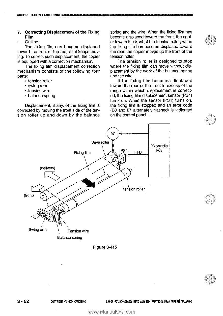
OPERATIONS AND TIMING K, 7. Correcting Displacement of the Fixing Film a. Outline The fixing film can become displaced toward the front or the rear as it keeps moving. To correct such displacement, the copier is equipped with a correction mechanism. The fixing film displacement correction mechanism consists of the following four parts: • tension roller • swing arm • tension wire • balance spring Displacement, if any, of the fixing film is corrected by moving the front side of the tension roller up and down by the balance spring and the wire. When the fixing film has become displaced toward the front, the copier lowers the front of the tension roller; when the fixing film has become displaced toward the rear, the copier moves up the front of the tension roller. The tension roller is designed to stop where the fixing film can move without displacement by the work of the balance spring and the wire. If the fixing film becomes displaced toward the rear or the front in excess of the range within which displacement is corrected, the fixing film displacement sensor (PS4) turns on. When the sensor (PS4) turns on, the fixing film is stopped and an error code (E0 and 07 alternately flashed) is indicated on the control panel. (delivery) Drive roller Fixing film PS4 FFD DC controller PCB (front) Tension roller Swing arm Tension wire Balance spring Figure 3-415 3 - 52 COPYRIGHT © 1994 CANON INC. CANON PC720114050/770 REV.O AUG.1994 PRINTEDIN JAPAN omplut AU JAPON)
-
 1
1 -
2
-
3
-
4
-
5
-
6
-
7
-
8
-
9
-
10
-
11
-
12
-
13
-
14
-
15
-
16
-
17
-
18
-
19
-
20
-
21
-
22
-
23
-
24
-
25
-
26
-
27
-
28
-
29
-
30
-
31
-
32
-
33
-
34
-
35
-
36
-
37
-
38
-
39
-
40
-
41
-
42
-
43
-
44
-
45
-
46
-
47
-
48
-
49
-
50
-
51
-
52
-
53
-
54
-
55
-
56
-
57
-
58
-
59
-
60
-
61
-
62
-
63
-
64
-
65
-
66
-
67
-
68
-
69
-
70
-
71
-
72
-
73
-
74
-
75
-
76
-
77
-
78
-
79
-
80
-
81
-
82
-
83
-
84
-
85
-
86
-
 87
87 -
 88
88 -
 89
89 -
 90
90 -
 91
91 -
 92
92 -
 93
93 -
 94
94 -
 95
95 -
 96
96 -
 97
97 -
98
-
99
-
100
-
101
-
102
-
103
-
104
-
105
-
106
-
107
-
108
-
109
-
110
-
111
-
112
-
113
-
114
-
115
-
116
-
117
-
118
-
119
-
120
-
121
-
122
-
123
-
124
-
125
-
126
-
127
-
128
-
129
-
130
-
131
-
132
-
133
-
134
-
135
-
136
-
137
-
138
-
139
-
140
-
141
-
142
-
143
-
144
-
145
-
146
-
147
-
148
-
149
-
150
-
151
-
152
-
153
-
154
-
155
-
156
-
157
-
158
-
159
-
160
-
161
-
162
-
163
-
164
-
165
-
166
-
167
-
168
-
169
-
170
-
171
-
172
-
173
-
174
-
175
-
176
-
177
-
178
-
179
-
180
-
181
-
182
-
183
-
184
-
185
-
186
-
187
-
188
-
189
-
190
-
191
-
192
-
193
-
194
-
195
-
196
-
197
-
198
-
199
-
200
 |
 |