Canon PC720 Service Manual - Page 93
Tension, tension
 |
View all Canon PC720 manuals
Add to My Manuals
Save this manual to your list of manuals |
Page 93 highlights
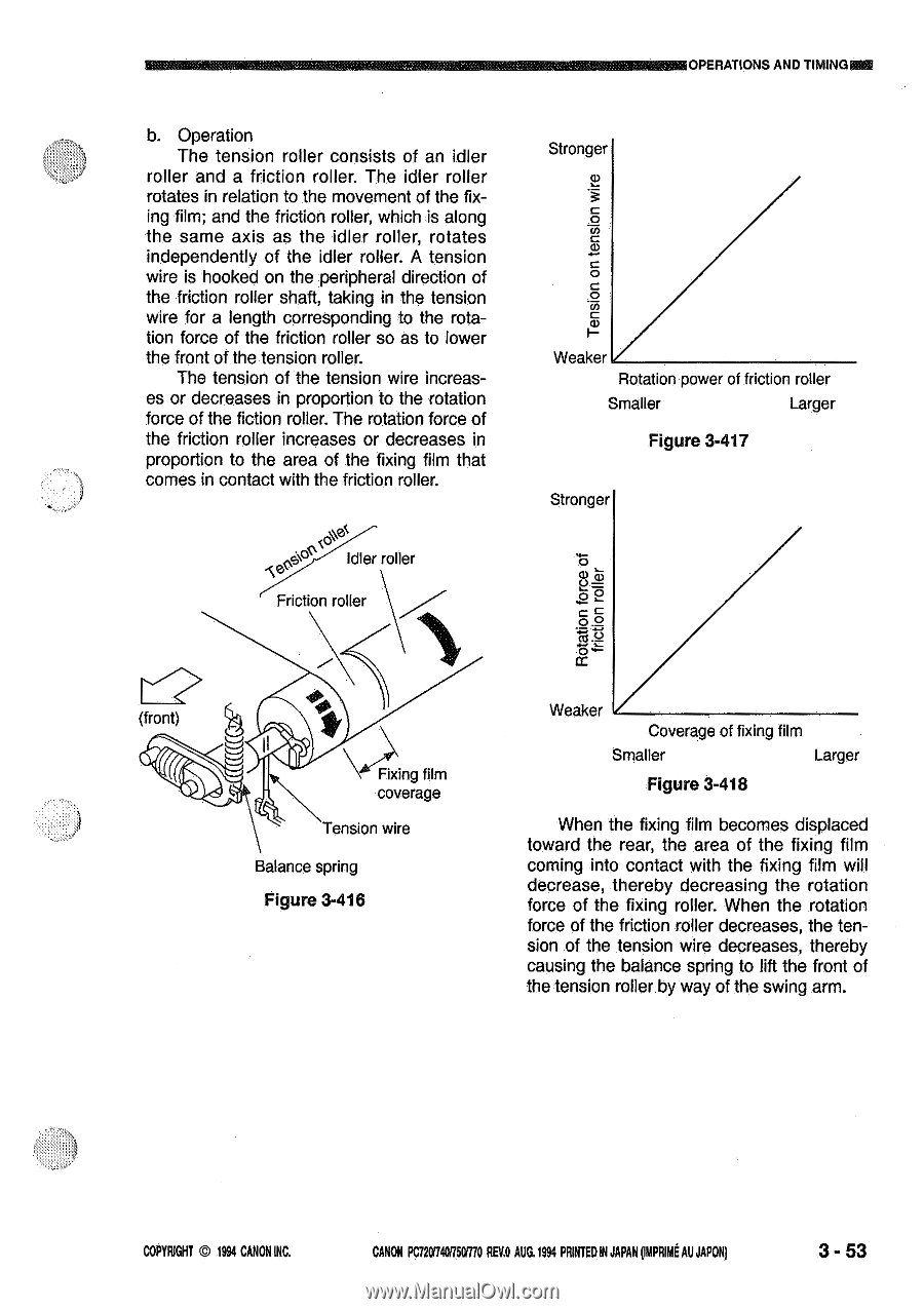
Mig§ OPERATIONS AND TIMING b. Operation The tension roller consists of an idler roller and a friction roller. The idler roller rotates in relation to the movement of the fixing film; and the friction roller, which is along the same axis as the idler roller, rotates independently of the idler roller. A tension wire is hooked on the peripheral direction of the friction roller shaft, taking in the tension wire for a length corresponding to the rotation force of the friction roller so as to lower the front of the tension roller. The tension of the tension wire increases or decreases in proportion to the rotation force of the fiction roller. The rotation force of the friction roller increases or decreases in proportion to the area of the fixing film that comes in contact with the friction roller. e6' ' Idler roller Friction roller (front) \\\* Fixing film coverage Tension wire Balance spring Figure 3-416 Stronger Tension on tension wire Weaker Rotation power of friction roller Smaller Larger Figure 3-417 Stronger 0 4-.) O 2 Cc 0c TTI c'3c 4= Weaker Coverage of fixing film Smaller Larger Figure 3-418 When the fixing film becomes displaced toward the rear, the area of the fixing film coming into contact with the fixing film will decrease, thereby decreasing the rotation force of the fixing roller. When the rotation force of the friction roller decreases, the tension of the tension wire decreases, thereby causing the balance spring to lift the front of the tension roller by way of the swing arm. COPYRIGHT 1994 CANONINC. CANON POT20174075EITTOREV.OAUG.1994 PRINTEDIN JAPAN(mPRimt AU JAPON) 3 - 53
-
 1
1 -
2
-
3
-
4
-
5
-
6
-
7
-
8
-
9
-
10
-
11
-
12
-
13
-
14
-
15
-
16
-
17
-
18
-
19
-
20
-
21
-
22
-
23
-
24
-
25
-
26
-
27
-
28
-
29
-
30
-
31
-
32
-
33
-
34
-
35
-
36
-
37
-
38
-
39
-
40
-
41
-
42
-
43
-
44
-
45
-
46
-
47
-
48
-
49
-
50
-
51
-
52
-
53
-
54
-
55
-
56
-
57
-
58
-
59
-
60
-
61
-
62
-
63
-
64
-
65
-
66
-
67
-
68
-
69
-
70
-
71
-
72
-
73
-
74
-
75
-
76
-
77
-
78
-
79
-
80
-
81
-
82
-
83
-
84
-
85
-
86
-
87
-
 88
88 -
 89
89 -
 90
90 -
 91
91 -
 92
92 -
 93
93 -
 94
94 -
 95
95 -
 96
96 -
 97
97 -
 98
98 -
99
-
100
-
101
-
102
-
103
-
104
-
105
-
106
-
107
-
108
-
109
-
110
-
111
-
112
-
113
-
114
-
115
-
116
-
117
-
118
-
119
-
120
-
121
-
122
-
123
-
124
-
125
-
126
-
127
-
128
-
129
-
130
-
131
-
132
-
133
-
134
-
135
-
136
-
137
-
138
-
139
-
140
-
141
-
142
-
143
-
144
-
145
-
146
-
147
-
148
-
149
-
150
-
151
-
152
-
153
-
154
-
155
-
156
-
157
-
158
-
159
-
160
-
161
-
162
-
163
-
164
-
165
-
166
-
167
-
168
-
169
-
170
-
171
-
172
-
173
-
174
-
175
-
176
-
177
-
178
-
179
-
180
-
181
-
182
-
183
-
184
-
185
-
186
-
187
-
188
-
189
-
190
-
191
-
192
-
193
-
194
-
195
-
196
-
197
-
198
-
199
-
200
 |
 |