Canon PC720 Service Manual - Page 73
Operations, Timing, Copyright, Canon, Rev.o, Aug.1994, Printed, Japan, Japon
 |
View all Canon PC720 manuals
Add to My Manuals
Save this manual to your list of manuals |
Page 73 highlights
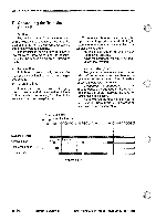
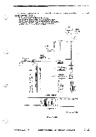
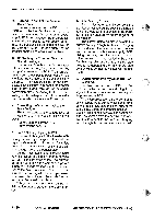
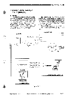
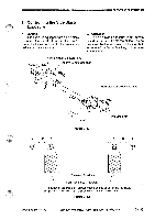
. .1OPERATIONS AND TIMING 4. AE Adjustment (VR102, VR103) Make the following adjustments whenev- er you have replaced the scanning lamp or the intensity/AE sensor PCB: Preparing for Adjustment • Obtain a newspaper whose print is as even as possible; avoid one with photos or with large headings. • Make sure you have adjusted the intensity of the scanning lamp. 1) Short the two jumper wires (JP3, JP4) on the DC controller PCB. P4 0 O JP3 741 O 5) Place a newspaper on the copyboard, and close the copyboard cover. 6) Turn VR102 so that the reading in the display is between b2 and bc. 0 12 JR109.122 VR101 VR101 fJ 212102 VR102 J. .1117 J102 .1104 .1105 .J109 0 VR102 Figure 3-321 7) Remove the newspaper from the copyboard, and place a stack of five sheets of copy paper on the copyboard glass instead; then, close the copyboard cover. 8) Turn VR103 on the DC controller PCB so that the reading in the display of the control panel is between 53 and 5d. 0 :0, 01 .12,100.123 V12151 122105 VR101 VR106 Figure 3-319 2) With the terminals shorted, turn on the power switch. • The scanning lamp should turn on, and the main motor (M1) should rotate. 3) Stop shorting the two terminals of the connector J116. 4) Turn VR103 on the DC controller PCB fully clockwise. 0 J112 1/1310.1 126105 VR101 VR106 /5 VRIO V21 0 44)1 J. J112 .1102 .1101 J105 0 VR103 Figure 3-320 J. .1112 .1102 J. 0 VR 03 Figure 3-322 COPYRIGHT 1994 CANON INC. CANON PC7201740f15V770 REV.O AUG.1994 PRINTED IN JAPAN ompromt AU JAPON) 3 - 33
-
 1
1 -
2
-
3
-
4
-
5
-
6
-
7
-
8
-
9
-
10
-
11
-
12
-
13
-
14
-
15
-
16
-
17
-
18
-
19
-
20
-
21
-
22
-
23
-
24
-
25
-
26
-
27
-
28
-
29
-
30
-
31
-
32
-
33
-
34
-
35
-
36
-
37
-
38
-
39
-
40
-
41
-
42
-
43
-
44
-
45
-
46
-
47
-
48
-
49
-
50
-
51
-
52
-
53
-
54
-
55
-
56
-
57
-
58
-
59
-
60
-
61
-
62
-
63
-
64
-
65
-
66
-
67
-
 68
68 -
 69
69 -
 70
70 -
 71
71 -
 72
72 -
 73
73 -
 74
74 -
 75
75 -
 76
76 -
 77
77 -
 78
78 -
79
-
80
-
81
-
82
-
83
-
84
-
85
-
86
-
87
-
88
-
89
-
90
-
91
-
92
-
93
-
94
-
95
-
96
-
97
-
98
-
99
-
100
-
101
-
102
-
103
-
104
-
105
-
106
-
107
-
108
-
109
-
110
-
111
-
112
-
113
-
114
-
115
-
116
-
117
-
118
-
119
-
120
-
121
-
122
-
123
-
124
-
125
-
126
-
127
-
128
-
129
-
130
-
131
-
132
-
133
-
134
-
135
-
136
-
137
-
138
-
139
-
140
-
141
-
142
-
143
-
144
-
145
-
146
-
147
-
148
-
149
-
150
-
151
-
152
-
153
-
154
-
155
-
156
-
157
-
158
-
159
-
160
-
161
-
162
-
163
-
164
-
165
-
166
-
167
-
168
-
169
-
170
-
171
-
172
-
173
-
174
-
175
-
176
-
177
-
178
-
179
-
180
-
181
-
182
-
183
-
184
-
185
-
186
-
187
-
188
-
189
-
190
-
191
-
192
-
193
-
194
-
195
-
196
-
197
-
198
-
199
-
200
 |
 |