Canon PC720 Service Manual - Page 131
Remove, insulating, sheet, screws, remove, motor, screw, voltage, terminal, Caution,
 |
View all Canon PC720 manuals
Add to My Manuals
Save this manual to your list of manuals |
Page 131 highlights
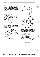
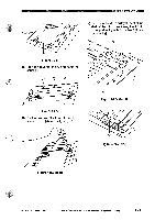
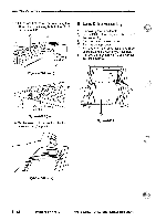
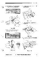
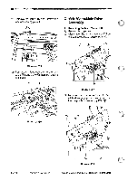
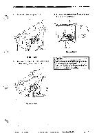
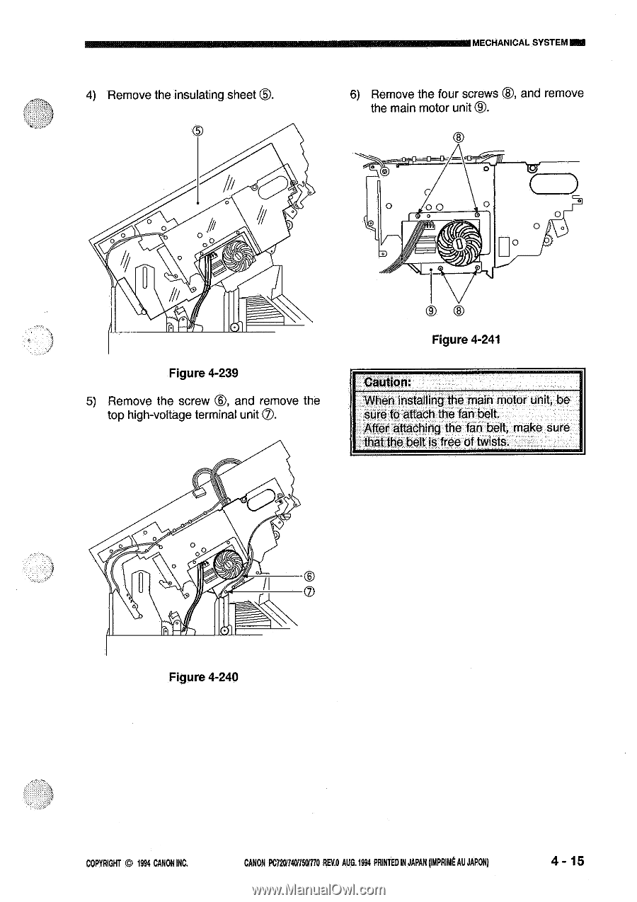
4) Remove the insulating sheet S. OS MECHANICAL SYSTEM! 6) Remove the four screws ®, and remove the main motor unit S. 0 0 /1/ U 11/ Figure 4-239 5) Remove the screw ®, and remove the top high-voltage terminal unit Q. 00 0 0 S Figure 4-241 Caution: When installing the main motor unit, be sure to attach the fan belt. After attaching the fan belt, make sure that the belt is free of twists. 00 0 U Figure 4-240 COPYRIGHT 1994 CANON INC. CANON PC720/7401150M0 REV.O AUG.1994 PRINTED IN JAPAN MARINE AU JAPOIN 4 - 15
-
 1
1 -
2
-
3
-
4
-
5
-
6
-
7
-
8
-
9
-
10
-
11
-
12
-
13
-
14
-
15
-
16
-
17
-
18
-
19
-
20
-
21
-
22
-
23
-
24
-
25
-
26
-
27
-
28
-
29
-
30
-
31
-
32
-
33
-
34
-
35
-
36
-
37
-
38
-
39
-
40
-
41
-
42
-
43
-
44
-
45
-
46
-
47
-
48
-
49
-
50
-
51
-
52
-
53
-
54
-
55
-
56
-
57
-
58
-
59
-
60
-
61
-
62
-
63
-
64
-
65
-
66
-
67
-
68
-
69
-
70
-
71
-
72
-
73
-
74
-
75
-
76
-
77
-
78
-
79
-
80
-
81
-
82
-
83
-
84
-
85
-
86
-
87
-
88
-
89
-
90
-
91
-
92
-
93
-
94
-
95
-
96
-
97
-
98
-
99
-
100
-
101
-
102
-
103
-
104
-
105
-
106
-
107
-
108
-
109
-
110
-
111
-
112
-
113
-
114
-
115
-
116
-
117
-
118
-
119
-
120
-
121
-
122
-
123
-
124
-
125
-
 126
126 -
 127
127 -
 128
128 -
 129
129 -
 130
130 -
 131
131 -
 132
132 -
 133
133 -
 134
134 -
 135
135 -
 136
136 -
137
-
138
-
139
-
140
-
141
-
142
-
143
-
144
-
145
-
146
-
147
-
148
-
149
-
150
-
151
-
152
-
153
-
154
-
155
-
156
-
157
-
158
-
159
-
160
-
161
-
162
-
163
-
164
-
165
-
166
-
167
-
168
-
169
-
170
-
171
-
172
-
173
-
174
-
175
-
176
-
177
-
178
-
179
-
180
-
181
-
182
-
183
-
184
-
185
-
186
-
187
-
188
-
189
-
190
-
191
-
192
-
193
-
194
-
195
-
196
-
197
-
198
-
199
-
200
 |
 |
MECHANICAL
SYSTEM!
4)
Remove
the
insulating
sheet
S.
6)
Remove
the
four
screws
®,
and
remove
the
main
motor
unit
S.
OS
00
/1
/
U
11/
0
0
Figure
4-239
5)
Remove
the
screw
®,
and
remove
the
top
high
-voltage
terminal
unit
Q.
0
U
00
Figure
4-240
0
S
Figure
4-241
0
Caution:
When
installing
the
main
motor
unit,
be
sure
to
attach
the
fan
belt.
After
attaching
the
fan
belt,
make
sure
that
the
belt
is
free
of
twists.
COPYRIGHT
1994
CANON
INC.
CANON
PC720/7401150M0
REV.O
AUG.1994
PRINTED
IN
JAPAN
MARINE
AU
JAPOIN
4
-
15