Canon PC720 Service Manual - Page 63
oscillation/amplitude
 |
View all Canon PC720 manuals
Add to My Manuals
Save this manual to your list of manuals |
Page 63 highlights
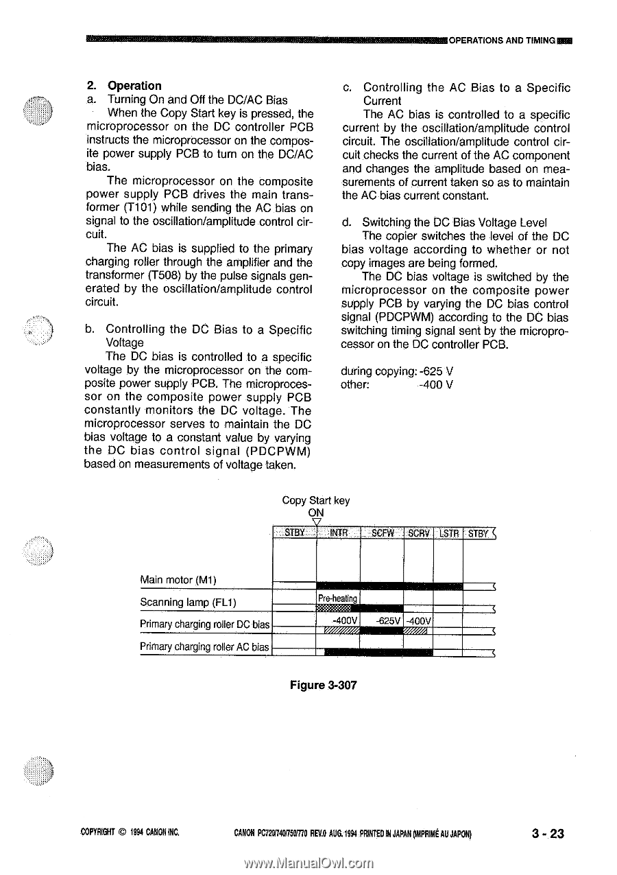
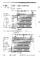
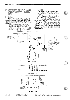
MWAIOPERATIONS AND TIMINGKM 2. Operation a. Turning On and Off the DC/AC Bias When the Copy Start key is pressed, the microprocessor on the DC controller PCB instructs the microprocessor on the composite power supply PCB to turn on the DC/AC bias. The microprocessor on the composite power supply PCB drives the main transformer (T101) while sending the AC bias on signal to the oscillation/amplitude control circuit. The AC bias is supplied to the primary charging roller through the amplifier and the transformer (T508) by the pulse signals generated by the oscillation/amplitude control circuit. b. Controlling the DC Bias to a Specific Voltage The DC bias is controlled to a specific voltage by the microprocessor on the composite power supply PCB. The microprocessor on the composite power supply PCB constantly monitors the DC voltage. The microprocessor serves to maintain the DC bias voltage to a constant value by varying the DC bias control signal (PDCPWM) based on measurements of voltage taken. c. Controlling the AC Bias to a Specific Current The AC bias is controlled to a specific current by the oscillation/amplitude control circuit. The oscillation/amplitude control circuit checks the current of the AC component and changes the amplitude based on measurements of current taken so as to maintain the AC bias current constant. d. Switching the DC Bias Voltage Level The copier switches the level of the DC bias voltage according to whether or not copy images are being formed. The DC bias voltage is switched by the microprocessor on the composite power supply PCB by varying the DC bias control signal (PDCPWM) according to the DC bias switching timing signal sent by the microprocessor on the DC controller PCB. during copying: -625 V other: -400 V Copy Start key ON STBY INTR SCFW SCRV LSTR STBY Main motor (M1) Scanning lamp (FL1) Primary charging roller DC bias Primary charging roller AC bias P e-heatn -400V -625V -400V Figure 3-307 COPYRIGHT O 1994 CANON INC. CANON PC720/740/750/770 REV.O AUG.1994 PRINTED IN JAPAN omput AU JAPON) 3 - 23
-
 1
1 -
2
-
3
-
4
-
5
-
6
-
7
-
8
-
9
-
10
-
11
-
12
-
13
-
14
-
15
-
16
-
17
-
18
-
19
-
20
-
21
-
22
-
23
-
24
-
25
-
26
-
27
-
28
-
29
-
30
-
31
-
32
-
33
-
34
-
35
-
36
-
37
-
38
-
39
-
40
-
41
-
42
-
43
-
44
-
45
-
46
-
47
-
48
-
49
-
50
-
51
-
52
-
53
-
54
-
55
-
56
-
57
-
 58
58 -
 59
59 -
 60
60 -
 61
61 -
 62
62 -
 63
63 -
 64
64 -
 65
65 -
 66
66 -
 67
67 -
 68
68 -
69
-
70
-
71
-
72
-
73
-
74
-
75
-
76
-
77
-
78
-
79
-
80
-
81
-
82
-
83
-
84
-
85
-
86
-
87
-
88
-
89
-
90
-
91
-
92
-
93
-
94
-
95
-
96
-
97
-
98
-
99
-
100
-
101
-
102
-
103
-
104
-
105
-
106
-
107
-
108
-
109
-
110
-
111
-
112
-
113
-
114
-
115
-
116
-
117
-
118
-
119
-
120
-
121
-
122
-
123
-
124
-
125
-
126
-
127
-
128
-
129
-
130
-
131
-
132
-
133
-
134
-
135
-
136
-
137
-
138
-
139
-
140
-
141
-
142
-
143
-
144
-
145
-
146
-
147
-
148
-
149
-
150
-
151
-
152
-
153
-
154
-
155
-
156
-
157
-
158
-
159
-
160
-
161
-
162
-
163
-
164
-
165
-
166
-
167
-
168
-
169
-
170
-
171
-
172
-
173
-
174
-
175
-
176
-
177
-
178
-
179
-
180
-
181
-
182
-
183
-
184
-
185
-
186
-
187
-
188
-
189
-
190
-
191
-
192
-
193
-
194
-
195
-
196
-
197
-
198
-
199
-
200
 |
 |