Canon PC720 Service Manual - Page 117
Externals
 |
View all Canon PC720 manuals
Add to My Manuals
Save this manual to your list of manuals |
Page 117 highlights
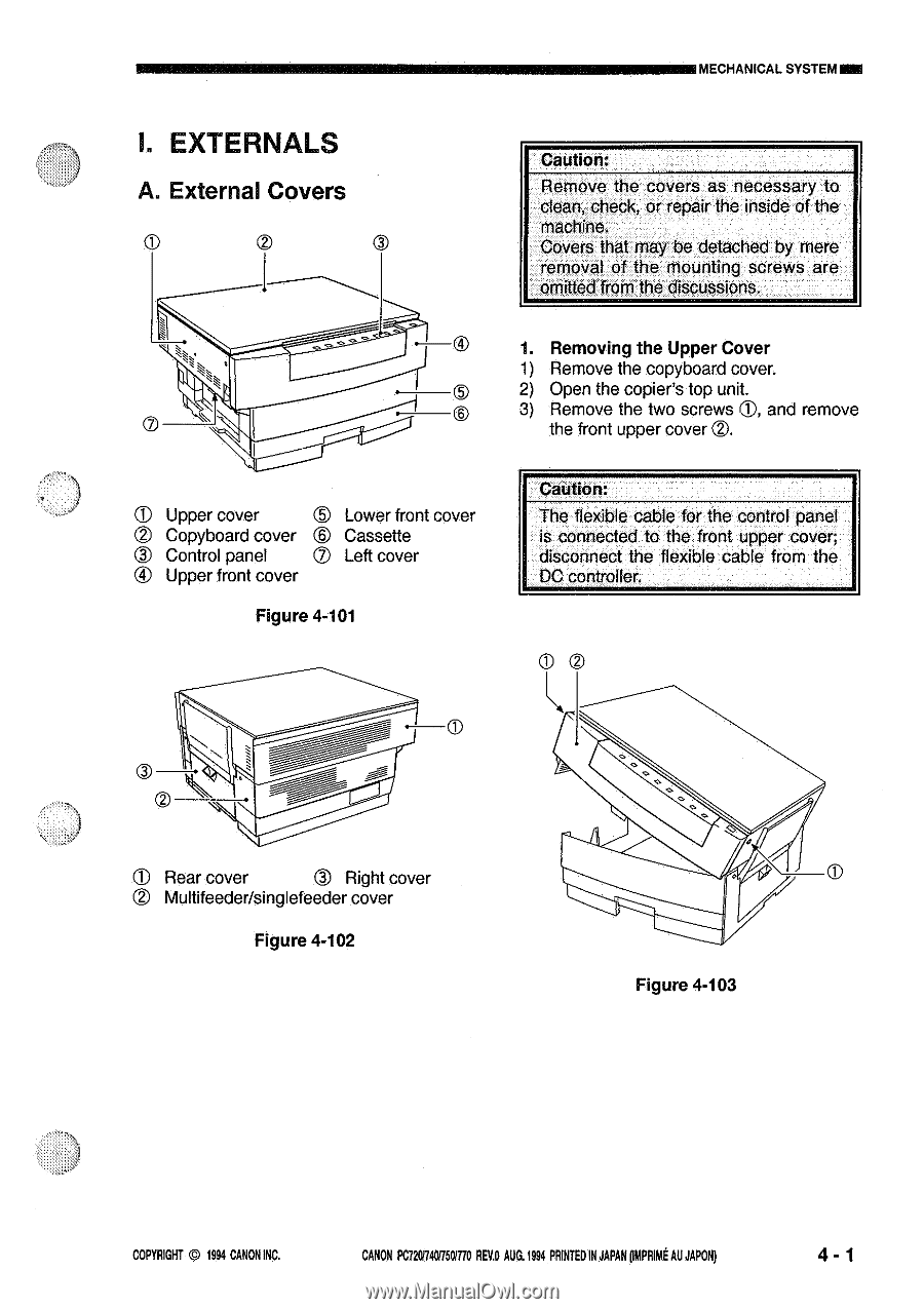
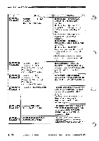
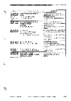
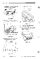
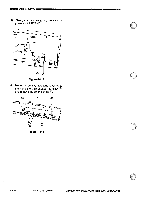
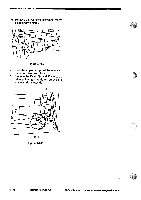
MECHANICAL SYSTEMINN I. EXTERNALS A. External Covers Caution: Remove the covers as necessary to clean, check, or repair the inside of the machine. Covers that may be detached by mere removal of the mounting screws are omitted from the discussions. • 1. Removing the Upper Cover 1) Remove the copyboard cover. • 2) Open the copier's top unit. 0 0 3) Remove the two screws 3, and remove the front upper cover ®. T Upper cover C) Lower front cover © Copyboard cover © Control panel Cassette Left cover ® Upper front cover Figure 4-101 Caution: The flexible cable for the control panel is connected to the front upper cover; disconnect the flexible cable from the DC controller. © Rear cover © Right cover • Multifeeder/singlefeeder cover Figure 4-102 Figure 4-103 COPYRIGHT © 1994 CANON INC. CANON PC720/7401150/770 REVD AUG.1994 PRINTED IN JAPAN pmPRiut AU JAPAN) 4 - 1
-
 1
1 -
2
-
3
-
4
-
5
-
6
-
7
-
8
-
9
-
10
-
11
-
12
-
13
-
14
-
15
-
16
-
17
-
18
-
19
-
20
-
21
-
22
-
23
-
24
-
25
-
26
-
27
-
28
-
29
-
30
-
31
-
32
-
33
-
34
-
35
-
36
-
37
-
38
-
39
-
40
-
41
-
42
-
43
-
44
-
45
-
46
-
47
-
48
-
49
-
50
-
51
-
52
-
53
-
54
-
55
-
56
-
57
-
58
-
59
-
60
-
61
-
62
-
63
-
64
-
65
-
66
-
67
-
68
-
69
-
70
-
71
-
72
-
73
-
74
-
75
-
76
-
77
-
78
-
79
-
80
-
81
-
82
-
83
-
84
-
85
-
86
-
87
-
88
-
89
-
90
-
91
-
92
-
93
-
94
-
95
-
96
-
97
-
98
-
99
-
100
-
101
-
102
-
103
-
104
-
105
-
106
-
107
-
108
-
109
-
110
-
111
-
 112
112 -
 113
113 -
 114
114 -
 115
115 -
 116
116 -
 117
117 -
 118
118 -
 119
119 -
 120
120 -
 121
121 -
 122
122 -
123
-
124
-
125
-
126
-
127
-
128
-
129
-
130
-
131
-
132
-
133
-
134
-
135
-
136
-
137
-
138
-
139
-
140
-
141
-
142
-
143
-
144
-
145
-
146
-
147
-
148
-
149
-
150
-
151
-
152
-
153
-
154
-
155
-
156
-
157
-
158
-
159
-
160
-
161
-
162
-
163
-
164
-
165
-
166
-
167
-
168
-
169
-
170
-
171
-
172
-
173
-
174
-
175
-
176
-
177
-
178
-
179
-
180
-
181
-
182
-
183
-
184
-
185
-
186
-
187
-
188
-
189
-
190
-
191
-
192
-
193
-
194
-
195
-
196
-
197
-
198
-
199
-
200
 |
 |