Canon PC720 Service Manual - Page 61
Controlling
 |
View all Canon PC720 manuals
Add to My Manuals
Save this manual to your list of manuals |
Page 61 highlights
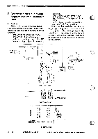
OPERATIONS AND TIMINGMN 3. Turning On and Off the Scanning Lamp a. Outline When pre-activation pre-heating is over, the microprocessor (Q101) on the DC controller PCB instructs the microprocessor (Q900) on the composite power supply PCB to generate the scanning lamp on signal (FLAON*). At this time, the fluorescent lamp driver circuit operates to apply the output of the primary side of the main transformer (T101) to both ends of the scanning lamp so as to turn on the scanning lamp at a high frequency. 4. Controlling the Intensity of the Scanning Lamp a. Outline The intensity of the scanning lamp is controlled by the microprocessor (O900) on the composite power supply PCB. The intensity sensor checks the intensity of the scanning lamp and generates activation power to suit the intensity. The microprocessor, on the other hand, finds out the intensity of the scanning lamp based on the activation power to send the scanning lamp on signal (FLON") to the on control circuit. b. Intensity Lower Than the Specified Value The microprocessor increases the duty ratio of the scanning lamp on signal (FLON*) sent to the fluorescent lamp driver. The fluorescent lamp driver, in turn, increases the current flowing to the scanning lamp, thereby increasing the intensity of the scanning lamp. c. Intensity Higher Than the Specified Value The microprocessor decreases the duty ratio of the scanning lamp on signal (FLOW) sent to the fluorescent lamp driver. The fluorescent lamp driver, in turn, decreases the current flowing to the scanning lamp, thereby decreasing the intensity of the scanning lamp. COPYRIGHT © 1994 CANON INC. CANON PC720/7401150770 REY.0 AUG.1994 PRINTED IN JAPAN 0mpuit AU JAPAN) 3 - 21
-
 1
1 -
2
-
3
-
4
-
5
-
6
-
7
-
8
-
9
-
10
-
11
-
12
-
13
-
14
-
15
-
16
-
17
-
18
-
19
-
20
-
21
-
22
-
23
-
24
-
25
-
26
-
27
-
28
-
29
-
30
-
31
-
32
-
33
-
34
-
35
-
36
-
37
-
38
-
39
-
40
-
41
-
42
-
43
-
44
-
45
-
46
-
47
-
48
-
49
-
50
-
51
-
52
-
53
-
54
-
55
-
 56
56 -
 57
57 -
 58
58 -
 59
59 -
 60
60 -
 61
61 -
 62
62 -
 63
63 -
 64
64 -
 65
65 -
 66
66 -
67
-
68
-
69
-
70
-
71
-
72
-
73
-
74
-
75
-
76
-
77
-
78
-
79
-
80
-
81
-
82
-
83
-
84
-
85
-
86
-
87
-
88
-
89
-
90
-
91
-
92
-
93
-
94
-
95
-
96
-
97
-
98
-
99
-
100
-
101
-
102
-
103
-
104
-
105
-
106
-
107
-
108
-
109
-
110
-
111
-
112
-
113
-
114
-
115
-
116
-
117
-
118
-
119
-
120
-
121
-
122
-
123
-
124
-
125
-
126
-
127
-
128
-
129
-
130
-
131
-
132
-
133
-
134
-
135
-
136
-
137
-
138
-
139
-
140
-
141
-
142
-
143
-
144
-
145
-
146
-
147
-
148
-
149
-
150
-
151
-
152
-
153
-
154
-
155
-
156
-
157
-
158
-
159
-
160
-
161
-
162
-
163
-
164
-
165
-
166
-
167
-
168
-
169
-
170
-
171
-
172
-
173
-
174
-
175
-
176
-
177
-
178
-
179
-
180
-
181
-
182
-
183
-
184
-
185
-
186
-
187
-
188
-
189
-
190
-
191
-
192
-
193
-
194
-
195
-
196
-
197
-
198
-
199
-
200
 |
 |