Canon PC720 Service Manual - Page 45
Outputs, Controller
 |
View all Canon PC720 manuals
Add to My Manuals
Save this manual to your list of manuals |
Page 45 highlights
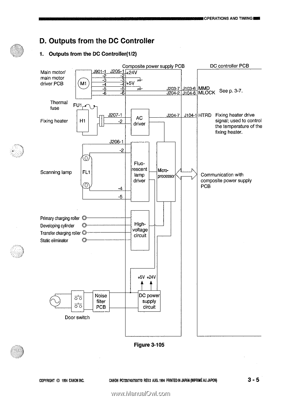
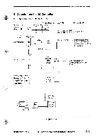
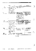
OPERATIONS AND TIMINGNM D. Outputs from the DC Controller 1. Outputs from the DC Controller(1/2) Main motor/ main motor driver PCB Thermal fuse FU1rr Fixing heater H1 Composite power supply PCB DC controller PCB J901-1 J205-1 .4 24v -2 -2 -3 -3 - -4 +5V -5 -5 -6 -6 J2O3-7 J1O3-6 MMD J204-2 J104-6 MLOCK See p. 3-7. - J207-1 -2 AC driver J206-1 -2 J2O4-7 J104-1 HTRD Fixing heater drive signal; used to control the temperature of the fixing heater. Scanning lamp FL1 Fluorescent lamp driver Microprocessor > Communication with composite power supply PCB Primary charging roller O Developing cylinder O Transfer charging roller O Static eliminator O Highvoltage circuit 00 Noise filter 00 PCB Door switch +5V +24V tt DC power supply circuit Figure 3-105 COPYRIGHT © 1994 CANON INC. CANON PC72017401750M0 REV.O AUG.1994 PRINTED IN JAPAN ommait AU JAPON) 3- 5
-
 1
1 -
2
-
3
-
4
-
5
-
6
-
7
-
8
-
9
-
10
-
11
-
12
-
13
-
14
-
15
-
16
-
17
-
18
-
19
-
20
-
21
-
22
-
23
-
24
-
25
-
26
-
27
-
28
-
29
-
30
-
31
-
32
-
33
-
34
-
35
-
36
-
37
-
38
-
39
-
 40
40 -
 41
41 -
 42
42 -
 43
43 -
 44
44 -
 45
45 -
 46
46 -
 47
47 -
 48
48 -
 49
49 -
 50
50 -
51
-
52
-
53
-
54
-
55
-
56
-
57
-
58
-
59
-
60
-
61
-
62
-
63
-
64
-
65
-
66
-
67
-
68
-
69
-
70
-
71
-
72
-
73
-
74
-
75
-
76
-
77
-
78
-
79
-
80
-
81
-
82
-
83
-
84
-
85
-
86
-
87
-
88
-
89
-
90
-
91
-
92
-
93
-
94
-
95
-
96
-
97
-
98
-
99
-
100
-
101
-
102
-
103
-
104
-
105
-
106
-
107
-
108
-
109
-
110
-
111
-
112
-
113
-
114
-
115
-
116
-
117
-
118
-
119
-
120
-
121
-
122
-
123
-
124
-
125
-
126
-
127
-
128
-
129
-
130
-
131
-
132
-
133
-
134
-
135
-
136
-
137
-
138
-
139
-
140
-
141
-
142
-
143
-
144
-
145
-
146
-
147
-
148
-
149
-
150
-
151
-
152
-
153
-
154
-
155
-
156
-
157
-
158
-
159
-
160
-
161
-
162
-
163
-
164
-
165
-
166
-
167
-
168
-
169
-
170
-
171
-
172
-
173
-
174
-
175
-
176
-
177
-
178
-
179
-
180
-
181
-
182
-
183
-
184
-
185
-
186
-
187
-
188
-
189
-
190
-
191
-
192
-
193
-
194
-
195
-
196
-
197
-
198
-
199
-
200
 |
 |