Canon PC720 Service Manual - Page 70
transformer/rectifier
 |
View all Canon PC720 manuals
Add to My Manuals
Save this manual to your list of manuals |
Page 70 highlights
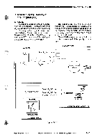
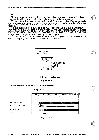
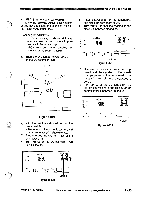
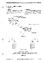
=OPERATIONS AND TIMING 2. Turning On and Off the Transfer Roller Bias The microprocessor on the DC controller PCB sends the transfer bias on signal to the microprocessor on the composite power supply PCB. In response, the microprocessor on the composite power supply generates the transfer bias on signal to drive the transformer (T302), thereby supplying the transfer charging roller with transfer bias. 3. Controlling the Transfer Bias to a Specific Voltage The transfer bias is controlled to a spe- cific voltage by the microprocessor on the composite power supply PCB. The microprocessor on the composite power supply PCB monitors the voltage of the transfer bias at all times. The microprocessor on the composite power supply PCB sends the transfer bias control signal through the pulse/DC conversion circuit according to the detected voltage to the voltage control circuit to maintain the transfer bias to a specific voltage. 4. Correcting the Voltage Level of the Transfer Bias The copier corrects the voltage level of the transfer bias in any of the following two ways: • before starting copying (ATVC) • after starting copying a. Before Starting Copying (ATVC) To correct changes in the transfer effi- ciency caused by changes in the environment or deterioration of the transfer roller, the copier automatically corrects the application voltage level of the transfer bias. During initial rotation after the Copy Start key is pressed, the copier feeds a specific current to the transfer roller. The current detection circuit on the composite power supply PCB sends measurements of the current to the microprocessor in the form of the current detection signal. The microprocessor determines the voltage to be applied to the transfer roller based on such data. This control is executed once during initial rotation after a press on the Copy Start key. b. After Starting Copying The copier automatically corrects the application voltage during copying operation to compensate for the changes in the transfer efficiency caused by different types of copy paper. The current detection circuit detects the current flowing through the transfer charging roller and sends the data to the microprocessor on the composite power supply PCB. Using the data, the microprocessor determines the voltage to be applied to the transfer charging roller and controls the DC bias voltage by generating the transfer DC bias control signal so that the voltage will be optimum. 5. Switching the Polarity of the DC Bias (cleaning) The microprocessor on the DC controller PCB sends the transfer bias switching timing signal to the microprocessor on the composite power supply PCB. The microprocessor on the composite power supply PCB, on the other hand, turns off the transfer DC bias on signal and, at the same time, sends the transfer positive DC bias on signal to the positive bias control circuit. The voltage from the positive bias control circuit is sent to the transfer charging roller through the transformer/rectifier circuit. 3 - 30 COPYRIGHT © 1994 CANON CANON PC72011401150= RBA AUG.1994 PRINTED IN JAPAN (IMPRNE AU JAPONI
-
 1
1 -
2
-
3
-
4
-
5
-
6
-
7
-
8
-
9
-
10
-
11
-
12
-
13
-
14
-
15
-
16
-
17
-
18
-
19
-
20
-
21
-
22
-
23
-
24
-
25
-
26
-
27
-
28
-
29
-
30
-
31
-
32
-
33
-
34
-
35
-
36
-
37
-
38
-
39
-
40
-
41
-
42
-
43
-
44
-
45
-
46
-
47
-
48
-
49
-
50
-
51
-
52
-
53
-
54
-
55
-
56
-
57
-
58
-
59
-
60
-
61
-
62
-
63
-
64
-
 65
65 -
 66
66 -
 67
67 -
 68
68 -
 69
69 -
 70
70 -
 71
71 -
 72
72 -
 73
73 -
 74
74 -
 75
75 -
76
-
77
-
78
-
79
-
80
-
81
-
82
-
83
-
84
-
85
-
86
-
87
-
88
-
89
-
90
-
91
-
92
-
93
-
94
-
95
-
96
-
97
-
98
-
99
-
100
-
101
-
102
-
103
-
104
-
105
-
106
-
107
-
108
-
109
-
110
-
111
-
112
-
113
-
114
-
115
-
116
-
117
-
118
-
119
-
120
-
121
-
122
-
123
-
124
-
125
-
126
-
127
-
128
-
129
-
130
-
131
-
132
-
133
-
134
-
135
-
136
-
137
-
138
-
139
-
140
-
141
-
142
-
143
-
144
-
145
-
146
-
147
-
148
-
149
-
150
-
151
-
152
-
153
-
154
-
155
-
156
-
157
-
158
-
159
-
160
-
161
-
162
-
163
-
164
-
165
-
166
-
167
-
168
-
169
-
170
-
171
-
172
-
173
-
174
-
175
-
176
-
177
-
178
-
179
-
180
-
181
-
182
-
183
-
184
-
185
-
186
-
187
-
188
-
189
-
190
-
191
-
192
-
193
-
194
-
195
-
196
-
197
-
198
-
199
-
200
 |
 |