Canon PC720 Service Manual - Page 115
Mechanical, System
 |
View all Canon PC720 manuals
Add to My Manuals
Save this manual to your list of manuals |
Page 115 highlights
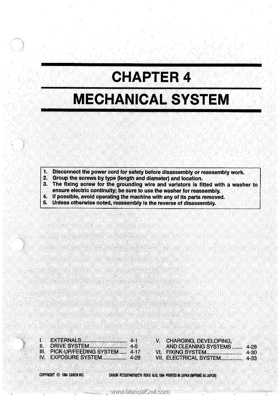
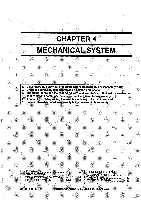
CHAPTER 4 MECHANICAL SYSTEM 1. Disconnect the power cord for safety before disassembly or reassembly work. 2. Group the screws by type (length and diameter) and location. 3. The fixing screw for the grounding wire and varistors is fitted with a washer to ensure electric continuity; be sure to use the washer for reassembly. 4. If possible, avoid operating the machine with any of its parts removed. 5. Unless otherwise noted, reassembly is the reverse of disassembly. I. EXTERNALS II. DRIVE SYSTEM III. PICK-UP/FEEDING SYSTEM IV. EXPOSURE SYSTEM 4-1 4-5 4-17 4-26 V. CHARGING, DEVELOPING, AND CLEANING SYSTEMS VI. FIXING SYSTEM VII. ELECTRICAL SYSTEM COPYRIGNT CO 1991 CANON NC. CANON PC/2074005770 REV.0 ma 1991 PRINTED IN JAPAN input AU JAPON, 4-28 4-30 4-33
-
 1
1 -
2
-
3
-
4
-
5
-
6
-
7
-
8
-
9
-
10
-
11
-
12
-
13
-
14
-
15
-
16
-
17
-
18
-
19
-
20
-
21
-
22
-
23
-
24
-
25
-
26
-
27
-
28
-
29
-
30
-
31
-
32
-
33
-
34
-
35
-
36
-
37
-
38
-
39
-
40
-
41
-
42
-
43
-
44
-
45
-
46
-
47
-
48
-
49
-
50
-
51
-
52
-
53
-
54
-
55
-
56
-
57
-
58
-
59
-
60
-
61
-
62
-
63
-
64
-
65
-
66
-
67
-
68
-
69
-
70
-
71
-
72
-
73
-
74
-
75
-
76
-
77
-
78
-
79
-
80
-
81
-
82
-
83
-
84
-
85
-
86
-
87
-
88
-
89
-
90
-
91
-
92
-
93
-
94
-
95
-
96
-
97
-
98
-
99
-
100
-
101
-
102
-
103
-
104
-
105
-
106
-
107
-
108
-
109
-
 110
110 -
 111
111 -
 112
112 -
 113
113 -
 114
114 -
 115
115 -
 116
116 -
 117
117 -
 118
118 -
 119
119 -
 120
120 -
121
-
122
-
123
-
124
-
125
-
126
-
127
-
128
-
129
-
130
-
131
-
132
-
133
-
134
-
135
-
136
-
137
-
138
-
139
-
140
-
141
-
142
-
143
-
144
-
145
-
146
-
147
-
148
-
149
-
150
-
151
-
152
-
153
-
154
-
155
-
156
-
157
-
158
-
159
-
160
-
161
-
162
-
163
-
164
-
165
-
166
-
167
-
168
-
169
-
170
-
171
-
172
-
173
-
174
-
175
-
176
-
177
-
178
-
179
-
180
-
181
-
182
-
183
-
184
-
185
-
186
-
187
-
188
-
189
-
190
-
191
-
192
-
193
-
194
-
195
-
196
-
197
-
198
-
199
-
200
 |
 |