Canon PC720 Service Manual - Page 55
Operations
 |
View all Canon PC720 manuals
Add to My Manuals
Save this manual to your list of manuals |
Page 55 highlights
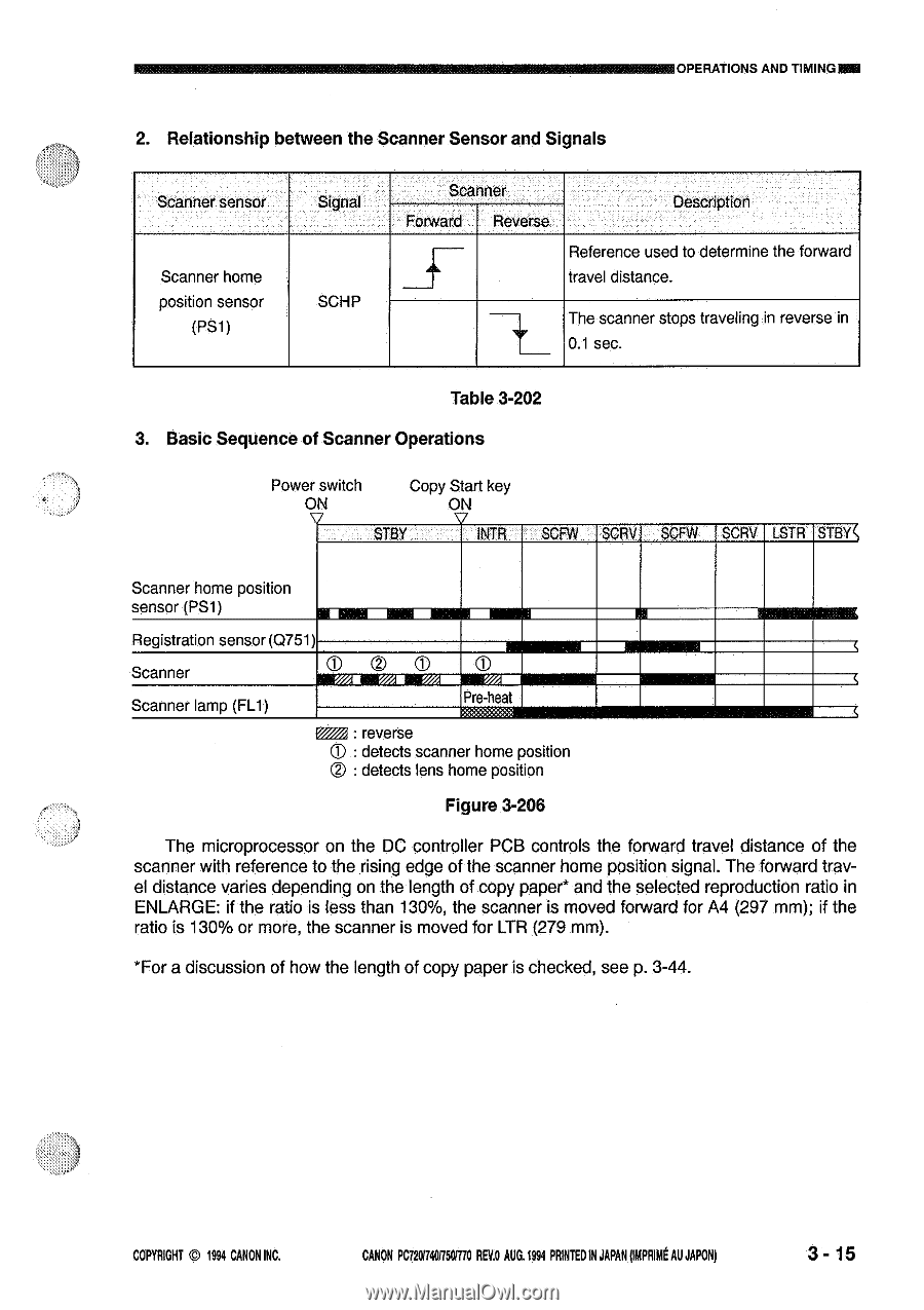
OPERATIONS AND TIMING= 2. Relationship between the Scanner Sensor and Signals Scanner sensor Scanner home position sensor (PS1) Signal SCHP Scanner Forward Reverse Description Reference used to determine the forward 5 travel distance. The scanner stops traveling in reverse in 0.1 sec. Table 3-202 3. Basic Sequence of Scanner Operations Power switch Copy Start key ON ON STBY V INTR I SCFW SCRV I SCFW SCHV LSTR STBYc Scanner home position sensor (PS1) Registration sensor (Q751) Scanner Scanner lamp (FL1) 0 rz/• rem •mm wym Pre-heat reverse C) : detects scanner home position C) : detects lens home position Figure 3-206 NE= The microprocessor on the DC controller PCB controls the forward travel distance of the scanner with reference to the rising edge of the scanner home position signal. The forward travel distance varies depending on the length of copy paper* and the selected reproduction ratio in ENLARGE: if the ratio is less than 130%, the scanner is moved forward for A4 (297 mm); if the ratio is 130% or more, the scanner is moved for LTR (279 mm). *For a discussion of how the length of copy paper is checked, see p. 3-44. COPYRIGHT © 1994 CANON INC. CANON PC720174017501170REV.O AUG.1994 PRINTED IN JAPAN (MPRIME AU JAPAN) 3 - 15
-
 1
1 -
2
-
3
-
4
-
5
-
6
-
7
-
8
-
9
-
10
-
11
-
12
-
13
-
14
-
15
-
16
-
17
-
18
-
19
-
20
-
21
-
22
-
23
-
24
-
25
-
26
-
27
-
28
-
29
-
30
-
31
-
32
-
33
-
34
-
35
-
36
-
37
-
38
-
39
-
40
-
41
-
42
-
43
-
44
-
45
-
46
-
47
-
48
-
49
-
 50
50 -
 51
51 -
 52
52 -
 53
53 -
 54
54 -
 55
55 -
 56
56 -
 57
57 -
 58
58 -
 59
59 -
 60
60 -
61
-
62
-
63
-
64
-
65
-
66
-
67
-
68
-
69
-
70
-
71
-
72
-
73
-
74
-
75
-
76
-
77
-
78
-
79
-
80
-
81
-
82
-
83
-
84
-
85
-
86
-
87
-
88
-
89
-
90
-
91
-
92
-
93
-
94
-
95
-
96
-
97
-
98
-
99
-
100
-
101
-
102
-
103
-
104
-
105
-
106
-
107
-
108
-
109
-
110
-
111
-
112
-
113
-
114
-
115
-
116
-
117
-
118
-
119
-
120
-
121
-
122
-
123
-
124
-
125
-
126
-
127
-
128
-
129
-
130
-
131
-
132
-
133
-
134
-
135
-
136
-
137
-
138
-
139
-
140
-
141
-
142
-
143
-
144
-
145
-
146
-
147
-
148
-
149
-
150
-
151
-
152
-
153
-
154
-
155
-
156
-
157
-
158
-
159
-
160
-
161
-
162
-
163
-
164
-
165
-
166
-
167
-
168
-
169
-
170
-
171
-
172
-
173
-
174
-
175
-
176
-
177
-
178
-
179
-
180
-
181
-
182
-
183
-
184
-
185
-
186
-
187
-
188
-
189
-
190
-
191
-
192
-
193
-
194
-
195
-
196
-
197
-
198
-
199
-
200
 |
 |