Cisco SGE2000 Configuration Guide - Page 126
Problem Solving Using a Subsystems Approach, Identifying Startup Problems
 |
View all Cisco SGE2000 manuals
Add to My Manuals
Save this manual to your list of manuals |
Page 126 highlights
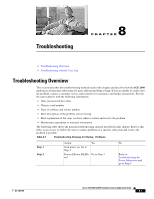
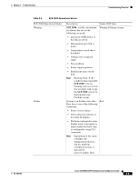
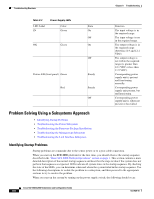
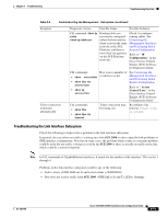
Troubleshooting Overview Chapter 8 Troubleshooting Table 8-3 LED Label IN Power Supply LEDs Color Green OK Green Power A/B (front panel) Green Red State On Off On Off Steady Steady Off Function The input voltage is in the required range. The input voltage is not in the required range. The output voltage is in the required range (between 11.9 and 12.1 VDC). The output voltage is not within the required range (is greater than 12.1 VDC or less than 11.9 VDC). Corresponding power supply unit is present and functioning normally. Corresponding power supply unit present, but malfunctioning. Corresponding power supply unit is either not present or has failed. Problem Solving Using a Subsystems Approach • Identifying Startup Problems • Troubleshooting the Power Subsystem • Troubleshooting the Firmware Package Installation • Troubleshooting the Management Subsystem • Troubleshooting the Link Interface Subsystem Identifying Startup Problems Startup problems are commonly due to the source power or to a poor cable connection. When you start up the SCE 2000 platform for the first time, you should observe the startup sequence described in the "Basic SCE 2000 Platform Operations" section on page 1. This section contains a more detailed description of the normal startup sequence and describes the steps to take if the system does not perform that sequence as expected. LEDs indicate all system states in the startup sequence. By checking the state of the LEDs, you can determine when and where the system failed in the startup sequence. Use the following descriptions to isolate the problem to a subsystem, and then proceed to the appropriate sections to try to resolve the problem. When you start up the system by turning on the power supply switch, the following should occur: Cisco SCE 2000 4xGBE Installation and Configuration Guide 8-6 OL-7824-06
-
 1
1 -
2
-
3
-
4
-
5
-
6
-
7
-
8
-
9
-
10
-
11
-
12
-
13
-
14
-
15
-
16
-
17
-
18
-
19
-
20
-
21
-
22
-
23
-
24
-
25
-
26
-
27
-
28
-
29
-
30
-
31
-
32
-
33
-
34
-
35
-
36
-
37
-
38
-
39
-
40
-
41
-
42
-
43
-
44
-
45
-
46
-
47
-
48
-
49
-
50
-
51
-
52
-
53
-
54
-
55
-
56
-
57
-
58
-
59
-
60
-
61
-
62
-
63
-
64
-
65
-
66
-
67
-
68
-
69
-
70
-
71
-
72
-
73
-
74
-
75
-
76
-
77
-
78
-
79
-
80
-
81
-
82
-
83
-
84
-
85
-
86
-
87
-
88
-
89
-
90
-
91
-
92
-
93
-
94
-
95
-
96
-
97
-
98
-
99
-
100
-
101
-
102
-
103
-
104
-
105
-
106
-
107
-
108
-
109
-
110
-
111
-
112
-
113
-
114
-
115
-
116
-
117
-
118
-
119
-
120
-
 121
121 -
 122
122 -
 123
123 -
 124
124 -
 125
125 -
 126
126 -
 127
127 -
 128
128 -
 129
129 -
 130
130 -
 131
131 -
132
-
133
-
134
-
135
-
136
-
137
-
138
-
139
-
140
-
141
-
142
 |
 |
