Cisco SGE2000 Configuration Guide - Page 31
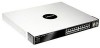
Cisco SCE 2000, 4xGBE, Single Link: Inline Topology, Dual link: Inline Installation
 |
View all Cisco SGE2000 manuals
Add to My Manuals
Save this manual to your list of manuals |
Page 31 highlights
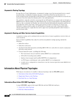
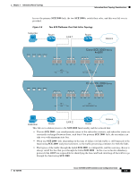
Chapter 3 Information About Topology Information About Topology Considerations Single Link: Inline Topology Typically, the SCE 2000 is connected in a full duplex GBE link between two devices (Router, BRAS, etc.). When the SCE 2000 is installed as an inline installation, it physically resides on the data link between the subscribers and the network. Figure 3-1 Single SCE Platform Single Link: In-line Topology PWR A PWR B STATUS BYPASS LINK RX TX LINK RX TX Cisco SCE 2000 Series 4xGBE LINK RX TX LINK RX TX RX MM TX RX MM TX GBE-1 SUB LINE NET RX MM TX RX MM TX GBE-2 SUB LINE/CASCADE NET Port 1 subscriber Port 2 network Network 92798 Subscriber Router Router When configuring the SCE 2000 , an inline installation is referred to as "inline" connection mode. Dual link: Inline Installation In this topology, one SCE 2000 is connected inline in two full duplex, GBE links. In case the two links are load-shared, asymmetrical routing might occur, and some of the flows may be split, i.e. the upstream packets of the flow go on one link, and the downstream packets go on the other link. When installed in this topology, the SCE 2000 completely overcomes this phenomenon, and provides its normal functionality as if asymmetrical routing were not occurring in the two links. OL-7824-06 Cisco SCE 2000 4xGBE Installation and Configuration Guide 3-5
-
 1
1 -
2
-
3
-
4
-
5
-
6
-
7
-
8
-
9
-
10
-
11
-
12
-
13
-
14
-
15
-
16
-
17
-
18
-
19
-
20
-
21
-
22
-
23
-
24
-
25
-
 26
26 -
 27
27 -
 28
28 -
 29
29 -
 30
30 -
 31
31 -
 32
32 -
 33
33 -
 34
34 -
 35
35 -
 36
36 -
37
-
38
-
39
-
40
-
41
-
42
-
43
-
44
-
45
-
46
-
47
-
48
-
49
-
50
-
51
-
52
-
53
-
54
-
55
-
56
-
57
-
58
-
59
-
60
-
61
-
62
-
63
-
64
-
65
-
66
-
67
-
68
-
69
-
70
-
71
-
72
-
73
-
74
-
75
-
76
-
77
-
78
-
79
-
80
-
81
-
82
-
83
-
84
-
85
-
86
-
87
-
88
-
89
-
90
-
91
-
92
-
93
-
94
-
95
-
96
-
97
-
98
-
99
-
100
-
101
-
102
-
103
-
104
-
105
-
106
-
107
-
108
-
109
-
110
-
111
-
112
-
113
-
114
-
115
-
116
-
117
-
118
-
119
-
120
-
121
-
122
-
123
-
124
-
125
-
126
-
127
-
128
-
129
-
130
-
131
-
132
-
133
-
134
-
135
-
136
-
137
-
138
-
139
-
140
-
141
-
142
 |
 |
