Cisco SGE2000 Configuration Guide - Page 41
Information About Site Requirement Guidelines, Airflow, Site Requirements
 |
View all Cisco SGE2000 manuals
Add to My Manuals
Save this manual to your list of manuals |
Page 41 highlights
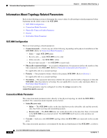
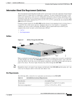
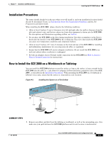
Chapter 4 Installation and Maintenance Information About Preparing to Install the SCE 2000 Platform Information About Site Requirement Guidelines The environmental monitoring functionality in the v protects the system and components from potential damage from over-voltage and over-temperature conditions. To ensure normal operation and to avoid unnecessary maintenance, plan your site configuration and prepare your site before installation. After installation, make sure the site maintains an ambient temperature of 41°F to 104°F (5°C to 40°C) with short term temperatures ranging from 23°F to 131°F (-5°C to 55°C), and keep the area around the SCE 2000 chassis free from dust. Planning a proper location for the SCE 2000 and the layout of your equipment rack or wiring closet is essential for successful system operation. Equipment placed too close together or inadequately ventilated can cause system over-heating. In addition, chassis panels made inaccessible by poor equipment placement can make system maintenance difficult. • Airflow • Site Requirements Airflow Figure 4-2 Left Airflow Through the SCE 2000 MNG 1 MNG 2 ALCITNIKV/E101/010000/ ALCITNIKV/E101/010000/ CONSOLE AUX PWR A PWR B STATUS BYPASS LINK RX TX LINK RX TX RX MM TX RX MM TX GBE-1 SUB LINE NET Cisco S4CxEG2B0E00 Series LINK RX TX LINK RX TX RX MM TX RX MM TX GBE-2 SUB LINE/CASCADE NET Right 92775 When you plan the location and layout of your equipment rack or wiring closet you need to consider how air flows though your system. The SCE 2000 draws cooling air in through the intake vents on the left side of the chassis, moves the air across the internal components, and out through the right side and rear panel of the chassis. The above figure illustrates the airflow through the SCE 2000 . Note Remember to leave a two inch (5 cm) clearance on both sides of the SCE 2000 and five inches (12.7 cm) at the rear for adequate airflow for the inlet and exhaust vents. Site Requirements The following tables contain the site requirement specifications for the SCE 2000 . Table 4-2 SCE 2000 Environmental Requirements Specification Temperature Short term temperatures* Acceptable Range nominal 41°F to 104°F (5°C to 40°C) 23°F to 131°F (-5°C to +55°C) OL-7824-06 Cisco SCE 2000 4xGBE Installation and Configuration Guide 4-3
-
 1
1 -
2
-
3
-
4
-
5
-
6
-
7
-
8
-
9
-
10
-
11
-
12
-
13
-
14
-
15
-
16
-
17
-
18
-
19
-
20
-
21
-
22
-
23
-
24
-
25
-
26
-
27
-
28
-
29
-
30
-
31
-
32
-
33
-
34
-
35
-
 36
36 -
 37
37 -
 38
38 -
 39
39 -
 40
40 -
 41
41 -
 42
42 -
 43
43 -
 44
44 -
 45
45 -
 46
46 -
47
-
48
-
49
-
50
-
51
-
52
-
53
-
54
-
55
-
56
-
57
-
58
-
59
-
60
-
61
-
62
-
63
-
64
-
65
-
66
-
67
-
68
-
69
-
70
-
71
-
72
-
73
-
74
-
75
-
76
-
77
-
78
-
79
-
80
-
81
-
82
-
83
-
84
-
85
-
86
-
87
-
88
-
89
-
90
-
91
-
92
-
93
-
94
-
95
-
96
-
97
-
98
-
99
-
100
-
101
-
102
-
103
-
104
-
105
-
106
-
107
-
108
-
109
-
110
-
111
-
112
-
113
-
114
-
115
-
116
-
117
-
118
-
119
-
120
-
121
-
122
-
123
-
124
-
125
-
126
-
127
-
128
-
129
-
130
-
131
-
132
-
133
-
134
-
135
-
136
-
137
-
138
-
139
-
140
-
141
-
142
 |
 |
