Cisco SGE2000 Configuration Guide - Page 40
Tools and Parts Required - rack mount kit
 |
View all Cisco SGE2000 manuals
Add to My Manuals
Save this manual to your list of manuals |
Page 40 highlights
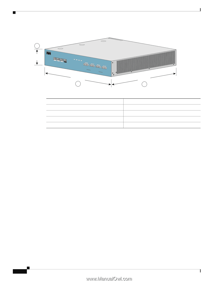
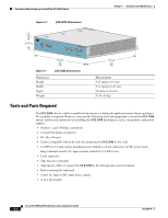
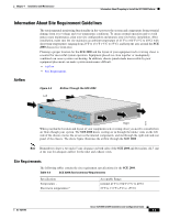
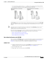
Information About Preparing to Install the SCE 2000 Platform Chapter 4 Installation and Maintenance Figure 4-1 SCE 2000 Dimensions 92776 1 3.47 in. MNG 1 MNG 2 ALCITNIKV/E101/010000/ ALCITNIKV/E101/010000/ CONSOLE AUX PWR A PWR B STATUS BYPASS LINK RX TX LINK RX TX RX MM TX RX MM TX GBE-1 SUB LINE NET Cisco S4CxEG2B0E00 Series LINK RX TX LINK RX TX RX MM TX RX MM TX GBE-2 SUB LINE/CASCADE NET 17.3 in. 2 Table 4-1 Dimension Height Width Depth Weight SCE 2000 Dimensions 17.7 in. 3 Measurement 3.47 inches (9.5 cm) 17.4 inches (4.43 cm) 18 inches (4.6 cm) 33 lb (15 kg) Tools and Parts Required The SCE 2000 chassis is fully assembled at the factory, including the application and software packages. No assembly is required. However, you need the following tools and equipment to install the SCE 2000 chassis and the rack-mount kit (if installing the SCE 2000 platform in a rack), fan modules, and power supplies: • Number 1 and 2 Phillips screwdriver • 1/4 inch flat-blade screwdriver • #¼" Hex Wrench • Screws compatible with your rack (for mounting the SCE 2000 to the rack) • 12 AWG or 2.5-mm copper installation wire with hex or loop connectors for DC power leads Ring terminals must be UL approved and suitable for 12 AWG wire. • Level (optional) • Tape measure (optional) • Appropriate cables to connect the SCE 2000 to the network and console terminal • Rack-mounting kit (optional) • A new AC-input or DC-input power supply • A new fan module Cisco SCE 2000 4xGBE Installation and Configuration Guide 4-2 OL-7824-06
-
 1
1 -
2
-
3
-
4
-
5
-
6
-
7
-
8
-
9
-
10
-
11
-
12
-
13
-
14
-
15
-
16
-
17
-
18
-
19
-
20
-
21
-
22
-
23
-
24
-
25
-
26
-
27
-
28
-
29
-
30
-
31
-
32
-
33
-
34
-
 35
35 -
 36
36 -
 37
37 -
 38
38 -
 39
39 -
 40
40 -
 41
41 -
 42
42 -
 43
43 -
 44
44 -
 45
45 -
46
-
47
-
48
-
49
-
50
-
51
-
52
-
53
-
54
-
55
-
56
-
57
-
58
-
59
-
60
-
61
-
62
-
63
-
64
-
65
-
66
-
67
-
68
-
69
-
70
-
71
-
72
-
73
-
74
-
75
-
76
-
77
-
78
-
79
-
80
-
81
-
82
-
83
-
84
-
85
-
86
-
87
-
88
-
89
-
90
-
91
-
92
-
93
-
94
-
95
-
96
-
97
-
98
-
99
-
100
-
101
-
102
-
103
-
104
-
105
-
106
-
107
-
108
-
109
-
110
-
111
-
112
-
113
-
114
-
115
-
116
-
117
-
118
-
119
-
120
-
121
-
122
-
123
-
124
-
125
-
126
-
127
-
128
-
129
-
130
-
131
-
132
-
133
-
134
-
135
-
136
-
137
-
138
-
139
-
140
-
141
-
142
 |
 |