Cisco SGE2000 Configuration Guide - Page 21
Table 2-3, SCE 2000 LED Groups, SCE 2000 Ports, LED Groups
 |
View all Cisco SGE2000 manuals
Add to My Manuals
Save this manual to your list of manuals |
Page 21 highlights
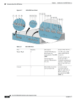
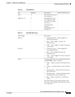
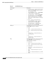
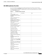
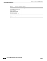
Chapter 2 Introduction to the SCE Platform Table 2-2 Port AUX SCE 2000 Ports Quantity 1 GBE ports 1-4 4 Table 2-3 SCE 2000 LED Groups LED Groups Power A Power B Status Information About The SCE Platform Description Connect This Port To... RS-232 RJ-45 port used by technicians GigabitEthernet ports for connecting to the line and/or cascading two devices CLI designation: interface GigabitEthernet 0/1 through 0/4 Description • Continuous green - Power supply A is functioning normally • Red - Power supply A present, but malfunctioning • Unlit - Power supply A is either not present or has failed. • Continuous green - Power supply B is functioning normally • Red - Power supply B present, but malfunctioning • Unlit - Power supply B is either not present or has failed. The Status LED indicates the operational status of the SCE 2000 system, as follows: • Unlit - indicates no power from either power unit. • Orange - indicates that the system is booting up. • Flashing green - indicates that the system is fully operational. • Flashing orange - indicates that the system is operational, but is in a warning state. • Red - indicates that there is a problem or failure Note that Alarms are hierarchical: Failure takes precedence over Warning, which takes precedence over operational. OL-7824-06 Cisco SCE 2000 4xGBE Installation and Configuration Guide 2-3
-
 1
1 -
2
-
3
-
4
-
5
-
6
-
7
-
8
-
9
-
10
-
11
-
12
-
13
-
14
-
15
-
 16
16 -
 17
17 -
 18
18 -
 19
19 -
 20
20 -
 21
21 -
 22
22 -
 23
23 -
 24
24 -
 25
25 -
 26
26 -
27
-
28
-
29
-
30
-
31
-
32
-
33
-
34
-
35
-
36
-
37
-
38
-
39
-
40
-
41
-
42
-
43
-
44
-
45
-
46
-
47
-
48
-
49
-
50
-
51
-
52
-
53
-
54
-
55
-
56
-
57
-
58
-
59
-
60
-
61
-
62
-
63
-
64
-
65
-
66
-
67
-
68
-
69
-
70
-
71
-
72
-
73
-
74
-
75
-
76
-
77
-
78
-
79
-
80
-
81
-
82
-
83
-
84
-
85
-
86
-
87
-
88
-
89
-
90
-
91
-
92
-
93
-
94
-
95
-
96
-
97
-
98
-
99
-
100
-
101
-
102
-
103
-
104
-
105
-
106
-
107
-
108
-
109
-
110
-
111
-
112
-
113
-
114
-
115
-
116
-
117
-
118
-
119
-
120
-
121
-
122
-
123
-
124
-
125
-
126
-
127
-
128
-
129
-
130
-
131
-
132
-
133
-
134
-
135
-
136
-
137
-
138
-
139
-
140
-
141
-
142
 |
 |
