Cisco SGE2000 Configuration Guide - Page 65
Connecting the Management Interfaces and Performing Initial System Configuration, How to Set Up the Local Console - console settings
 |
View all Cisco SGE2000 manuals
Add to My Manuals
Save this manual to your list of manuals |
Page 65 highlights
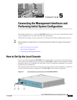
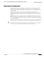
5 C H A P T E R Connecting the Management Interfaces and Performing Initial System Configuration This chapter explains how to connect the SCE 2000 platform to a local console and perform the initial system configuration via the setup wizard that runs automatically. Additionally, this chapter contains instructions for cabling the Fast Ethernet Management interfaces. Note When installing a cascaded system, it is extremely important to follow the sequence of procedures outlined. • How to Set Up the Local Console • Initial System Configuration • Connecting the Management Interface How to Set Up the Local Console Even if you will be managing the SCE 2000 from a remote location, you must first connect the unit to a local console and configure the initial settings for the SCE 2000 to support remote management. When the initial connection is established, the setup utility will run automatically, prompting you to perform the initial system configuration. This section provides instructions for setting up your local terminal at your workstation, to enable you to perform the initial system configuration of the SCE 2000 system using the setup utility. Figure 5-1 Connecting the Local Console to the SCE 2000 CON Port 92790 1 MNG 1 MNG 2 ALCITNIKV/E101/010000/ ALCITNIKV/E101/010000/ CONSOLE AUX 2 3 PWR A PWR B STATUS BYPASS LINK RX TX LINK RX TX RX MM TX RX MM TX GBE-1 SUB LINE NET Cisco S4CxEG2B0E00 Series LINK RX TX LINK RX TX RX MM TX RX MM TX GBE-2 SUB LINE/CASCADE NET OL-7824-06 Cisco SCE 2000 4xGBE Installation and Configuration Guide 5-1
-
 1
1 -
2
-
3
-
4
-
5
-
6
-
7
-
8
-
9
-
10
-
11
-
12
-
13
-
14
-
15
-
16
-
17
-
18
-
19
-
20
-
21
-
22
-
23
-
24
-
25
-
26
-
27
-
28
-
29
-
30
-
31
-
32
-
33
-
34
-
35
-
36
-
37
-
38
-
39
-
40
-
41
-
42
-
43
-
44
-
45
-
46
-
47
-
48
-
49
-
50
-
51
-
52
-
53
-
54
-
55
-
56
-
57
-
58
-
59
-
 60
60 -
 61
61 -
 62
62 -
 63
63 -
 64
64 -
 65
65 -
 66
66 -
 67
67 -
 68
68 -
 69
69 -
 70
70 -
71
-
72
-
73
-
74
-
75
-
76
-
77
-
78
-
79
-
80
-
81
-
82
-
83
-
84
-
85
-
86
-
87
-
88
-
89
-
90
-
91
-
92
-
93
-
94
-
95
-
96
-
97
-
98
-
99
-
100
-
101
-
102
-
103
-
104
-
105
-
106
-
107
-
108
-
109
-
110
-
111
-
112
-
113
-
114
-
115
-
116
-
117
-
118
-
119
-
120
-
121
-
122
-
123
-
124
-
125
-
126
-
127
-
128
-
129
-
130
-
131
-
132
-
133
-
134
-
135
-
136
-
137
-
138
-
139
-
140
-
141
-
142
 |
 |
