HP 5100 Service Manual - Page 118
Top cover removal 2 of 3
 |
UPC - 808736092500
View all HP 5100 manuals
Add to My Manuals
Save this manual to your list of manuals |
Page 118 highlights
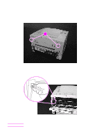
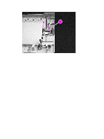
Note 2 Remove two self-tapping screws on the top of the chassis (callout 1). 3 Remove the two self-tapping screws on the top portion of the back of the printer (callout 2). The rear cover needs to be opened or removed before you can gain access to the screws. 2 12 Figure 41. Top cover removal (2 of 3) 4 The cable that connects the control panel to the printer chassis is on the left side of the top cover. Tilt the cover to the left as you lift it. Be careful not to stress the cable as you loosen the cover. 5 Disconnect the control panel cable from the printer chassis by grasping the wires and gently pulling the connector straight up. Figure 42. Top cover removal (3 of 3) 6 Remove the top cover. 116 Removing and replacing parts Q1860-90918
-
 1
1 -
2
-
3
-
4
-
5
-
6
-
7
-
8
-
9
-
10
-
11
-
12
-
13
-
14
-
15
-
16
-
17
-
18
-
19
-
20
-
21
-
22
-
23
-
24
-
25
-
26
-
27
-
28
-
29
-
30
-
31
-
32
-
33
-
34
-
35
-
36
-
37
-
38
-
39
-
40
-
41
-
42
-
43
-
44
-
45
-
46
-
47
-
48
-
49
-
50
-
51
-
52
-
53
-
54
-
55
-
56
-
57
-
58
-
59
-
60
-
61
-
62
-
63
-
64
-
65
-
66
-
67
-
68
-
69
-
70
-
71
-
72
-
73
-
74
-
75
-
76
-
77
-
78
-
79
-
80
-
81
-
82
-
83
-
84
-
85
-
86
-
87
-
88
-
89
-
90
-
91
-
92
-
93
-
94
-
95
-
96
-
97
-
98
-
99
-
100
-
101
-
102
-
103
-
104
-
105
-
106
-
107
-
108
-
109
-
110
-
111
-
112
-
 113
113 -
 114
114 -
 115
115 -
 116
116 -
 117
117 -
 118
118 -
 119
119 -
 120
120 -
 121
121 -
 122
122 -
 123
123 -
124
-
125
-
126
-
127
-
128
-
129
-
130
-
131
-
132
-
133
-
134
-
135
-
136
-
137
-
138
-
139
-
140
-
141
-
142
-
143
-
144
-
145
-
146
-
147
-
148
-
149
-
150
-
151
-
152
-
153
-
154
-
155
-
156
-
157
-
158
-
159
-
160
-
161
-
162
-
163
-
164
-
165
-
166
-
167
-
168
-
169
-
170
-
171
-
172
-
173
-
174
-
175
-
176
-
177
-
178
-
179
-
180
-
181
-
182
-
183
-
184
-
185
-
186
-
187
-
188
-
189
-
190
-
191
-
192
-
193
-
194
-
195
-
196
-
197
-
198
-
199
-
200
-
201
-
202
-
203
-
204
-
205
-
206
-
207
-
208
-
209
-
210
-
211
-
212
-
213
-
214
-
215
-
216
-
217
-
218
-
219
-
220
-
221
-
222
-
223
-
224
-
225
-
226
-
227
-
228
-
229
-
230
-
231
-
232
-
233
-
234
-
235
-
236
-
237
-
238
-
239
-
240
-
241
-
242
-
243
-
244
-
245
-
246
-
247
-
248
-
249
-
250
-
251
-
252
-
253
-
254
-
255
-
256
-
257
-
258
-
259
-
260
-
261
-
262
-
263
-
264
-
265
-
266
-
267
-
268
-
269
-
270
-
271
-
272
-
273
-
274
-
275
-
276
-
277
-
278
-
279
-
280
-
281
-
282
-
283
-
284
-
285
-
286
-
287
-
288
-
289
-
290
-
291
-
292
-
293
-
294
-
295
-
296
-
297
-
298
-
299
-
300
-
301
-
302
-
303
-
304
-
305
-
306
-
307
-
308
-
309
-
310
-
311
-
312
-
313
-
314
 |
 |

116
Removing and replacing parts
Q1860-90918
2
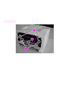
Remove two self-tapping screws on the top of the chassis (callout 1).
3
Remove the two self-tapping screws on the top portion of the back of the printer (callout 2).
Note
The rear cover needs to be opened or removed before you can gain access to the screws.
Figure 41.
Top cover removal (2 of 3)
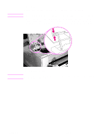
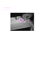
4
The cable that connects the control panel to the printer chassis is on the left side of the top
cover. Tilt the cover to the left as you lift it. Be careful not to stress the cable as you loosen
the cover.
5
Disconnect the control panel cable from the printer chassis by grasping the wires and gently
pulling the connector straight up.
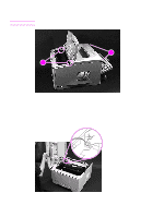
Figure 42.
Top cover removal (3 of 3)
6
Remove the top cover.
2
2
1
2