HP 5100 Service Manual - Page 162
Registration assembly removal 2 of 2, When you reinstall the clutch
 |
UPC - 808736092500
View all HP 5100 manuals
Add to My Manuals
Save this manual to your list of manuals |
Page 162 highlights
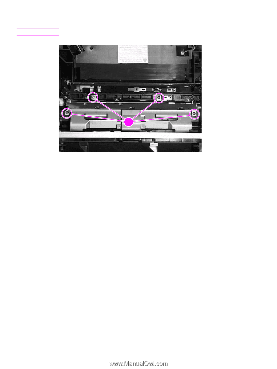
Note 4 Remove the four self-tapping screws (callout 2) inside the chassis. Lift up the small green handle of the registration assembly to gain access to two of these screws. 2 Figure 93. Registration assembly removal (2 of 2) 5 Lift the registration assembly out of the chassis. To reinstall When you reinstall the registration assembly, be careful to align the flags in the base as you reinstall the assembly. When you reinstall the clutch, orient the flat spot in the shaft with the clutch. When you slide the clutch on the shaft, make sure that the metal alignment tab is seated on the printer frame. Also make sure that the cable is situated away from the registration assembly. 160 Removing and replacing parts Q1860-90918
-
 1
1 -
2
-
3
-
4
-
5
-
6
-
7
-
8
-
9
-
10
-
11
-
12
-
13
-
14
-
15
-
16
-
17
-
18
-
19
-
20
-
21
-
22
-
23
-
24
-
25
-
26
-
27
-
28
-
29
-
30
-
31
-
32
-
33
-
34
-
35
-
36
-
37
-
38
-
39
-
40
-
41
-
42
-
43
-
44
-
45
-
46
-
47
-
48
-
49
-
50
-
51
-
52
-
53
-
54
-
55
-
56
-
57
-
58
-
59
-
60
-
61
-
62
-
63
-
64
-
65
-
66
-
67
-
68
-
69
-
70
-
71
-
72
-
73
-
74
-
75
-
76
-
77
-
78
-
79
-
80
-
81
-
82
-
83
-
84
-
85
-
86
-
87
-
88
-
89
-
90
-
91
-
92
-
93
-
94
-
95
-
96
-
97
-
98
-
99
-
100
-
101
-
102
-
103
-
104
-
105
-
106
-
107
-
108
-
109
-
110
-
111
-
112
-
113
-
114
-
115
-
116
-
117
-
118
-
119
-
120
-
121
-
122
-
123
-
124
-
125
-
126
-
127
-
128
-
129
-
130
-
131
-
132
-
133
-
134
-
135
-
136
-
137
-
138
-
139
-
140
-
141
-
142
-
143
-
144
-
145
-
146
-
147
-
148
-
149
-
150
-
151
-
152
-
153
-
154
-
155
-
156
-
 157
157 -
 158
158 -
 159
159 -
 160
160 -
 161
161 -
 162
162 -
 163
163 -
 164
164 -
 165
165 -
 166
166 -
 167
167 -
168
-
169
-
170
-
171
-
172
-
173
-
174
-
175
-
176
-
177
-
178
-
179
-
180
-
181
-
182
-
183
-
184
-
185
-
186
-
187
-
188
-
189
-
190
-
191
-
192
-
193
-
194
-
195
-
196
-
197
-
198
-
199
-
200
-
201
-
202
-
203
-
204
-
205
-
206
-
207
-
208
-
209
-
210
-
211
-
212
-
213
-
214
-
215
-
216
-
217
-
218
-
219
-
220
-
221
-
222
-
223
-
224
-
225
-
226
-
227
-
228
-
229
-
230
-
231
-
232
-
233
-
234
-
235
-
236
-
237
-
238
-
239
-
240
-
241
-
242
-
243
-
244
-
245
-
246
-
247
-
248
-
249
-
250
-
251
-
252
-
253
-
254
-
255
-
256
-
257
-
258
-
259
-
260
-
261
-
262
-
263
-
264
-
265
-
266
-
267
-
268
-
269
-
270
-
271
-
272
-
273
-
274
-
275
-
276
-
277
-
278
-
279
-
280
-
281
-
282
-
283
-
284
-
285
-
286
-
287
-
288
-
289
-
290
-
291
-
292
-
293
-
294
-
295
-
296
-
297
-
298
-
299
-
300
-
301
-
302
-
303
-
304
-
305
-
306
-
307
-
308
-
309
-
310
-
311
-
312
-
313
-
314
 |
 |
160
Removing and replacing parts
Q1860-90918
4
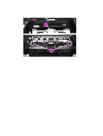
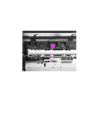
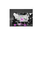
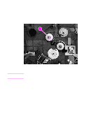
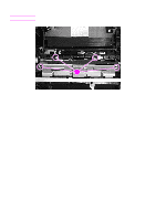
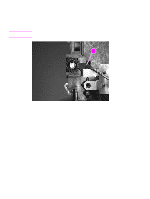
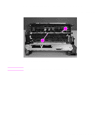
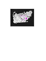
Remove the four self-tapping screws (callout 2) inside the chassis.
Note
Lift up the small green handle of the registration assembly to gain access to two of these screws.
Figure 93.
Registration assembly removal (2 of 2)
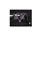
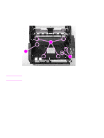
5
Lift the registration assembly out of the chassis.
To reinstall
When you reinstall the registration assembly, be careful to align the flags in the base as you
reinstall the assembly.
When you reinstall the clutch, orient the flat spot in the shaft with the clutch. When you slide the
clutch on the shaft, make sure that the metal alignment tab is seated on the printer frame. Also
make sure that the cable is situated away from the registration assembly.
2
2