HP 5100 Service Manual - Page 176
Optional 500-sheet feeder, Covers and base frame
 |
UPC - 808736092500
View all HP 5100 manuals
Add to My Manuals
Save this manual to your list of manuals |
Page 176 highlights
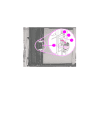
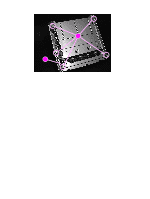
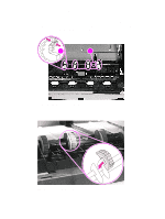
Optional 500-sheet feeder Covers and base frame 1 Use the flat-blade screwdriver to press down four locking tabs (callout 1) and then remove the right and left auxiliary covers (callout 2). 2 Use the flat-blade screwdriver to press down the two locking tabs (callout 3) on the top of the front cover (callout 4) and then remove the front cover by reaching under the lip of the cover and pulling it toward you, one end at a time. 2 2 12 32 Figure 111. 42 500-sheet feeder removal (1 of 2, top view) 3 Remove the paper-size sensing springs (callout 5) by disengaging the locking tabs from the left frame assembly. 52 Figure 112. Paper-size spring assembly removal 174 Removing and replacing parts Q1860-90918
-
 1
1 -
2
-
3
-
4
-
5
-
6
-
7
-
8
-
9
-
10
-
11
-
12
-
13
-
14
-
15
-
16
-
17
-
18
-
19
-
20
-
21
-
22
-
23
-
24
-
25
-
26
-
27
-
28
-
29
-
30
-
31
-
32
-
33
-
34
-
35
-
36
-
37
-
38
-
39
-
40
-
41
-
42
-
43
-
44
-
45
-
46
-
47
-
48
-
49
-
50
-
51
-
52
-
53
-
54
-
55
-
56
-
57
-
58
-
59
-
60
-
61
-
62
-
63
-
64
-
65
-
66
-
67
-
68
-
69
-
70
-
71
-
72
-
73
-
74
-
75
-
76
-
77
-
78
-
79
-
80
-
81
-
82
-
83
-
84
-
85
-
86
-
87
-
88
-
89
-
90
-
91
-
92
-
93
-
94
-
95
-
96
-
97
-
98
-
99
-
100
-
101
-
102
-
103
-
104
-
105
-
106
-
107
-
108
-
109
-
110
-
111
-
112
-
113
-
114
-
115
-
116
-
117
-
118
-
119
-
120
-
121
-
122
-
123
-
124
-
125
-
126
-
127
-
128
-
129
-
130
-
131
-
132
-
133
-
134
-
135
-
136
-
137
-
138
-
139
-
140
-
141
-
142
-
143
-
144
-
145
-
146
-
147
-
148
-
149
-
150
-
151
-
152
-
153
-
154
-
155
-
156
-
157
-
158
-
159
-
160
-
161
-
162
-
163
-
164
-
165
-
166
-
167
-
168
-
169
-
170
-
 171
171 -
 172
172 -
 173
173 -
 174
174 -
 175
175 -
 176
176 -
 177
177 -
 178
178 -
 179
179 -
 180
180 -
 181
181 -
182
-
183
-
184
-
185
-
186
-
187
-
188
-
189
-
190
-
191
-
192
-
193
-
194
-
195
-
196
-
197
-
198
-
199
-
200
-
201
-
202
-
203
-
204
-
205
-
206
-
207
-
208
-
209
-
210
-
211
-
212
-
213
-
214
-
215
-
216
-
217
-
218
-
219
-
220
-
221
-
222
-
223
-
224
-
225
-
226
-
227
-
228
-
229
-
230
-
231
-
232
-
233
-
234
-
235
-
236
-
237
-
238
-
239
-
240
-
241
-
242
-
243
-
244
-
245
-
246
-
247
-
248
-
249
-
250
-
251
-
252
-
253
-
254
-
255
-
256
-
257
-
258
-
259
-
260
-
261
-
262
-
263
-
264
-
265
-
266
-
267
-
268
-
269
-
270
-
271
-
272
-
273
-
274
-
275
-
276
-
277
-
278
-
279
-
280
-
281
-
282
-
283
-
284
-
285
-
286
-
287
-
288
-
289
-
290
-
291
-
292
-
293
-
294
-
295
-
296
-
297
-
298
-
299
-
300
-
301
-
302
-
303
-
304
-
305
-
306
-
307
-
308
-
309
-
310
-
311
-
312
-
313
-
314
 |
 |

174
Removing and replacing parts
Q1860-90918
Optional 500-sheet feeder
Covers and base frame
1
Use the flat-blade screwdriver to press down four locking tabs (callout 1) and then remove
the right and left auxiliary covers (callout 2).
2
Use the flat-blade screwdriver to press down the two locking tabs (callout 3) on the top of the
front cover (callout 4) and then remove the front cover by reaching under the lip of the cover
and pulling it toward you, one end at a time.
Figure 111.
500-sheet feeder removal (1 of 2, top view)
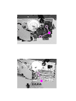
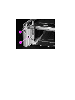
3
Remove the paper-size sensing springs (callout 5) by disengaging the locking tabs from the
left frame assembly.
Figure 112.
Paper-size spring assembly removal
2
2
2
2
1
4
2
2
2
3
2
5