HP 5100 Service Manual - Page 134
Top margin adjustment, Adjusting the top margin
 |
UPC - 808736092500
View all HP 5100 manuals
Add to My Manuals
Save this manual to your list of manuals |
Page 134 highlights
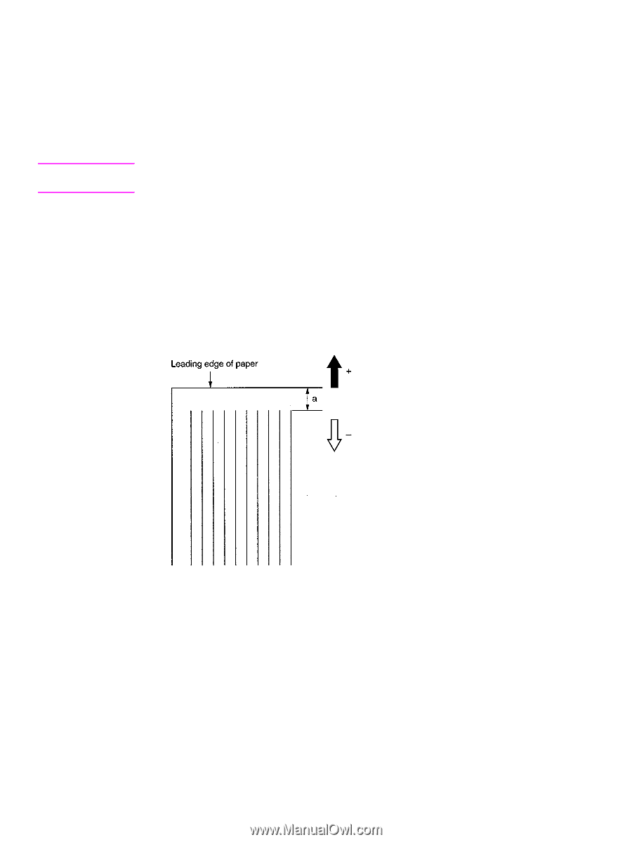
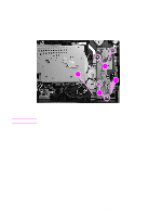
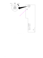
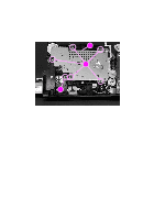
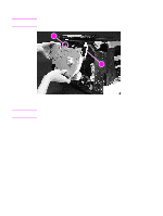
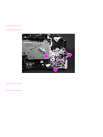
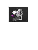
Note Top margin adjustment After replacing the paper-handling PCA, readjust the top margin. This adjustment is also necessary if the top margin of test prints that are made after laser/scanner or dc controller replacement is not 2.0 mm. The following steps comprise the adjustment procedure: 1 After you set the VR401 on the paper-handling PCA to the center position (+/-0), place letteror A4-sized paper in the tray. Press the test-print switch to make several test prints. The test-print switch is also located on the paper-handling PCA (a hole in the Tray 1 cavity allows access); see figure 62. 2 Measure the length from the leading edge of the paper to the print pattern ("a" in figure 61). Measure all the test prints and calculate the average. 3 Adjust the VR401 so that the calculated value in step 2 becomes 2.0 mm. The pattern image shifts in the "+" direction in figure 61 if the VR401 (see figure 62) is turned clockwise, and in the "-" direction if the VR401 is turned counterclockwise. Turning the VR401 one scale shifts the pattern approximately 0.8 mm. For example, if the average value calculated in step 2 is 2.8 mm, then the difference is 0.8 mm; turn the VR401 clockwise for one scale. 4 Make several test prints again, and perform step 2. Make sure that the top margin is 2.0 mm. If the value is not 2.0 mm, then repeat these steps as necessary. Figure 61. Adjusting the top margin 132 Removing and replacing parts Q1860-90918
-
 1
1 -
2
-
3
-
4
-
5
-
6
-
7
-
8
-
9
-
10
-
11
-
12
-
13
-
14
-
15
-
16
-
17
-
18
-
19
-
20
-
21
-
22
-
23
-
24
-
25
-
26
-
27
-
28
-
29
-
30
-
31
-
32
-
33
-
34
-
35
-
36
-
37
-
38
-
39
-
40
-
41
-
42
-
43
-
44
-
45
-
46
-
47
-
48
-
49
-
50
-
51
-
52
-
53
-
54
-
55
-
56
-
57
-
58
-
59
-
60
-
61
-
62
-
63
-
64
-
65
-
66
-
67
-
68
-
69
-
70
-
71
-
72
-
73
-
74
-
75
-
76
-
77
-
78
-
79
-
80
-
81
-
82
-
83
-
84
-
85
-
86
-
87
-
88
-
89
-
90
-
91
-
92
-
93
-
94
-
95
-
96
-
97
-
98
-
99
-
100
-
101
-
102
-
103
-
104
-
105
-
106
-
107
-
108
-
109
-
110
-
111
-
112
-
113
-
114
-
115
-
116
-
117
-
118
-
119
-
120
-
121
-
122
-
123
-
124
-
125
-
126
-
127
-
128
-
 129
129 -
 130
130 -
 131
131 -
 132
132 -
 133
133 -
 134
134 -
 135
135 -
 136
136 -
 137
137 -
 138
138 -
 139
139 -
140
-
141
-
142
-
143
-
144
-
145
-
146
-
147
-
148
-
149
-
150
-
151
-
152
-
153
-
154
-
155
-
156
-
157
-
158
-
159
-
160
-
161
-
162
-
163
-
164
-
165
-
166
-
167
-
168
-
169
-
170
-
171
-
172
-
173
-
174
-
175
-
176
-
177
-
178
-
179
-
180
-
181
-
182
-
183
-
184
-
185
-
186
-
187
-
188
-
189
-
190
-
191
-
192
-
193
-
194
-
195
-
196
-
197
-
198
-
199
-
200
-
201
-
202
-
203
-
204
-
205
-
206
-
207
-
208
-
209
-
210
-
211
-
212
-
213
-
214
-
215
-
216
-
217
-
218
-
219
-
220
-
221
-
222
-
223
-
224
-
225
-
226
-
227
-
228
-
229
-
230
-
231
-
232
-
233
-
234
-
235
-
236
-
237
-
238
-
239
-
240
-
241
-
242
-
243
-
244
-
245
-
246
-
247
-
248
-
249
-
250
-
251
-
252
-
253
-
254
-
255
-
256
-
257
-
258
-
259
-
260
-
261
-
262
-
263
-
264
-
265
-
266
-
267
-
268
-
269
-
270
-
271
-
272
-
273
-
274
-
275
-
276
-
277
-
278
-
279
-
280
-
281
-
282
-
283
-
284
-
285
-
286
-
287
-
288
-
289
-
290
-
291
-
292
-
293
-
294
-
295
-
296
-
297
-
298
-
299
-
300
-
301
-
302
-
303
-
304
-
305
-
306
-
307
-
308
-
309
-
310
-
311
-
312
-
313
-
314
 |
 |