HP rp3440 Installation Guide, Seventh Edition - HP 9000 rp3410 and HP 9000 rp3 - Page 18
Control Panel, Front View
 |
View all HP rp3440 manuals
Add to My Manuals
Save this manual to your list of manuals |
Page 18 highlights
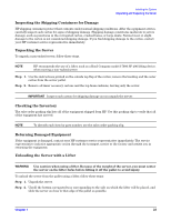
Installing the System Introduction • If installing a hot-pluggable component, complete the required software intervention prior to removing the component. • If installing an assembly that is neither hot-swappable, nor hot-pluggable, disconnect the power cable from the external server power receptacle. WARNING Ensure that the server is powered off and all power sources are disconnected from the server prior to removing or installing server hardware unless you are removing or installing a hot-swappable or hot-pluggable component. Voltages are present at various locations within the server whenever a dc power source is connected. This voltage is present even when the main power switch is turned off. Failure to observe this warning can result in personal injury or damage to equipment. • Do not wear loose clothing that can snag or catch on the server or on other items. • Do not wear clothing subject to static charge build up, such as wool or synthetic materials. • If installing an internal assembly, wear an antistatic wrist strap and use a grounding mat, such as those included in the Electrically Conductive Field Service Grounding Kit (HP 9300-1609). • Handle accessory boards and components by the edges only. Do not touch any metal-edge connectors or any electrical components on accessory boards. Control Panel The control panel of the HP 9000 rp3410 or rp3440 server provides the controls and indicators commonly used for operation. Figure 1-5 Front View Control Panel DVD Drive HDD 3 HDD 2 HDD 1 System Product Label (pull-out) 18 Chapter 1
-
 1
1 -
2
-
3
-
4
-
5
-
6
-
7
-
8
-
9
-
10
-
11
-
12
-
 13
13 -
 14
14 -
 15
15 -
 16
16 -
 17
17 -
 18
18 -
 19
19 -
 20
20 -
 21
21 -
 22
22 -
 23
23 -
24
-
25
-
26
-
27
-
28
-
29
-
30
-
31
-
32
-
33
-
34
-
35
-
36
-
37
-
38
-
39
-
40
-
41
-
42
-
43
-
44
-
45
-
46
-
47
-
48
-
49
-
50
-
51
-
52
-
53
-
54
-
55
-
56
-
57
-
58
-
59
-
60
-
61
-
62
-
63
-
64
-
65
-
66
-
67
-
68
-
69
-
70
-
71
-
72
-
73
-
74
-
75
-
76
-
77
-
78
-
79
-
80
-
81
-
82
-
83
-
84
-
85
-
86
-
87
-
88
-
89
-
90
-
91
-
92
-
93
-
94
-
95
-
96
 |
 |