HP rp3440 Installation Guide, Seventh Edition - HP 9000 rp3410 and HP 9000 rp3 - Page 45
Routing the Turbofan Power Cables through Heatsink Posts
 |
View all HP rp3440 manuals
Add to My Manuals
Save this manual to your list of manuals |
Page 45 highlights
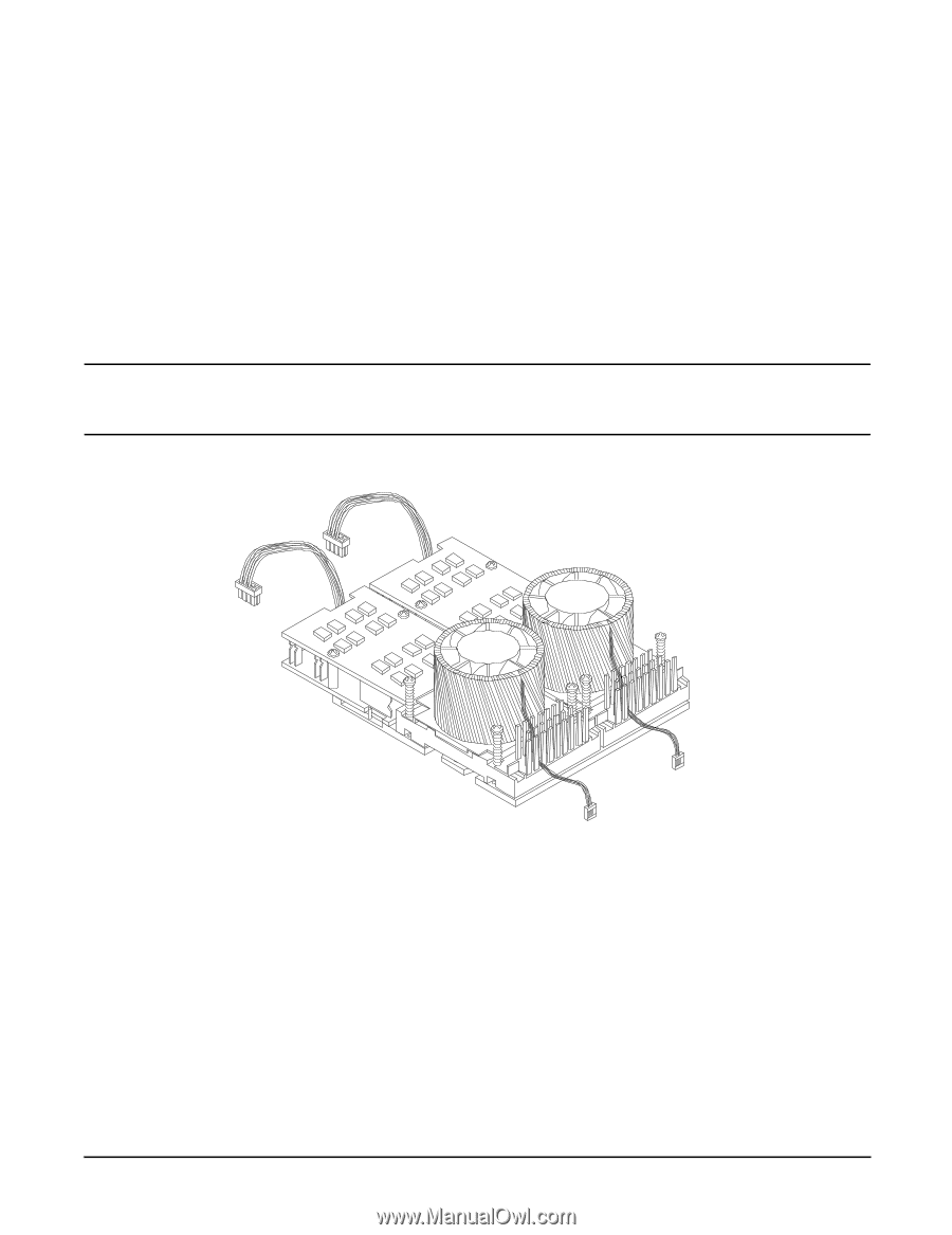
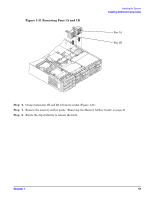
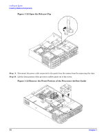
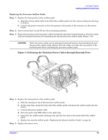
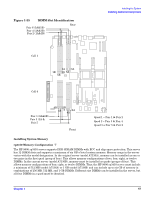
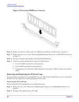
Installing the System Installing Additional Components Replacing the Processor Airflow Guide Step 1. Replace the front portion of the airflow guide: a. Align the release latch of the front half of the airflow guide over the release latch post and snap it in place. b. Connect the power connector on the front portion of the guide to the connector on the system board. Step 2. Insert system fans 1A and 1B into their mounting positions. Step 3. Route the processor turbo fan power cables through the processor heatsink posts so that the cables will not be pinched between the heatsink posts and the processor airflow guide (Figure 1-34). CAUTION Turbo fan power cables can be damaged if pinched between the heatsink posts and the processor airflow guide. Ensure that the cables are below the top surface of the heatsink posts before installing the processor airflow guide. Figure 1-34 Routing the Turbofan Power Cables through Heatsink Posts Step 4. Replace the main portion of the airflow guide: a. Hold the opening on top of the processor airflow guide. b. At the same time, grasp the back end of the airflow guide and insert the airflow guide into the server. c. Connect the power module cable. d. Place the power and IDE cables in the cable clips. e. Insert the two airflow guide retaining tabs into the two slots on the front half of the airflow guide. f. Replace the memory airflow guide. "Replacing the Memory Airflow Guide" on page 42 Step 5. Replace the server cover. Chapter 1 45
-
 1
1 -
2
-
3
-
4
-
5
-
6
-
7
-
8
-
9
-
10
-
11
-
12
-
13
-
14
-
15
-
16
-
17
-
18
-
19
-
20
-
21
-
22
-
23
-
24
-
25
-
26
-
27
-
28
-
29
-
30
-
31
-
32
-
33
-
34
-
35
-
36
-
37
-
38
-
39
-
 40
40 -
 41
41 -
 42
42 -
 43
43 -
 44
44 -
 45
45 -
 46
46 -
 47
47 -
 48
48 -
 49
49 -
 50
50 -
51
-
52
-
53
-
54
-
55
-
56
-
57
-
58
-
59
-
60
-
61
-
62
-
63
-
64
-
65
-
66
-
67
-
68
-
69
-
70
-
71
-
72
-
73
-
74
-
75
-
76
-
77
-
78
-
79
-
80
-
81
-
82
-
83
-
84
-
85
-
86
-
87
-
88
-
89
-
90
-
91
-
92
-
93
-
94
-
95
-
96
 |
 |