HP rp3440 Installation Guide, Seventh Edition - HP 9000 rp3410 and HP 9000 rp3 - Page 63
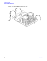
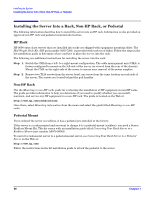
Routing the Turbofan Power Cables through Heatsink Posts, Step 15.
 |
View all HP rp3440 manuals
Add to My Manuals
Save this manual to your list of manuals |
Page 63 highlights
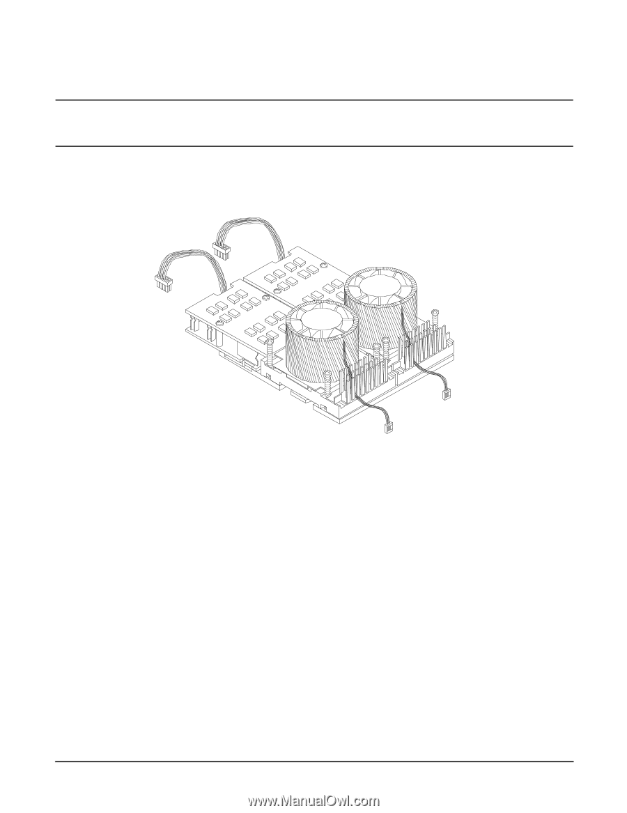
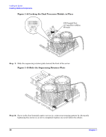
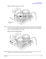
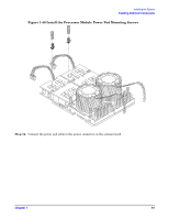
Installing the System Installing Additional Components CAUTION Turbo fan power cables can be damaged if pinched between the heatsink posts and the processor airflow guide. Ensure that the cables are below the top surface of the heatsink posts before installing the processor airflow guide. Step 15. Route the turbo fan power cables through the heatsink posts so that the cables will not be pinched when the processor airflow guide is set in place. Figure 1-51 Routing the Turbofan Power Cables through Heatsink Posts Step 16. Connect the turbo fan power cable to the system board. Step 17. Replace the processor airflow guide. (See "Replacing the Processor Airflow Guide" on page 45.) Step 18. Replace the memory airflow guide. (See "Replacing the Memory Airflow Guide" on page 42.) Step 19. Replace the cover. (See "Removing and Replacing the Top Cover on a Rack-Mounted Server" on page 26.) Step 20. Reconnect power and external cables and turn on the server. Step 21. Verify processor installation by using the system utilities. • Use the iLO MP commands to verify operation • Use the BCH commands to verify operation • Use MAKODIAG provided by the offline diagnostic environment to exercise the processor added Chapter 1 63
-
 1
1 -
2
-
3
-
4
-
5
-
6
-
7
-
8
-
9
-
10
-
11
-
12
-
13
-
14
-
15
-
16
-
17
-
18
-
19
-
20
-
21
-
22
-
23
-
24
-
25
-
26
-
27
-
28
-
29
-
30
-
31
-
32
-
33
-
34
-
35
-
36
-
37
-
38
-
39
-
40
-
41
-
42
-
43
-
44
-
45
-
46
-
47
-
48
-
49
-
50
-
51
-
52
-
53
-
54
-
55
-
56
-
57
-
 58
58 -
 59
59 -
 60
60 -
 61
61 -
 62
62 -
 63
63 -
 64
64 -
 65
65 -
 66
66 -
 67
67 -
 68
68 -
69
-
70
-
71
-
72
-
73
-
74
-
75
-
76
-
77
-
78
-
79
-
80
-
81
-
82
-
83
-
84
-
85
-
86
-
87
-
88
-
89
-
90
-
91
-
92
-
93
-
94
-
95
-
96
 |
 |