HP rp3440 Installation Guide, Seventh Edition - HP 9000 rp3410 and HP 9000 rp3 - Page 91
Table 1-16, System LED States, Power and System LEDs, LAN LEDs, System LED, State
 |
View all HP rp3440 manuals
Add to My Manuals
Save this manual to your list of manuals |
Page 91 highlights
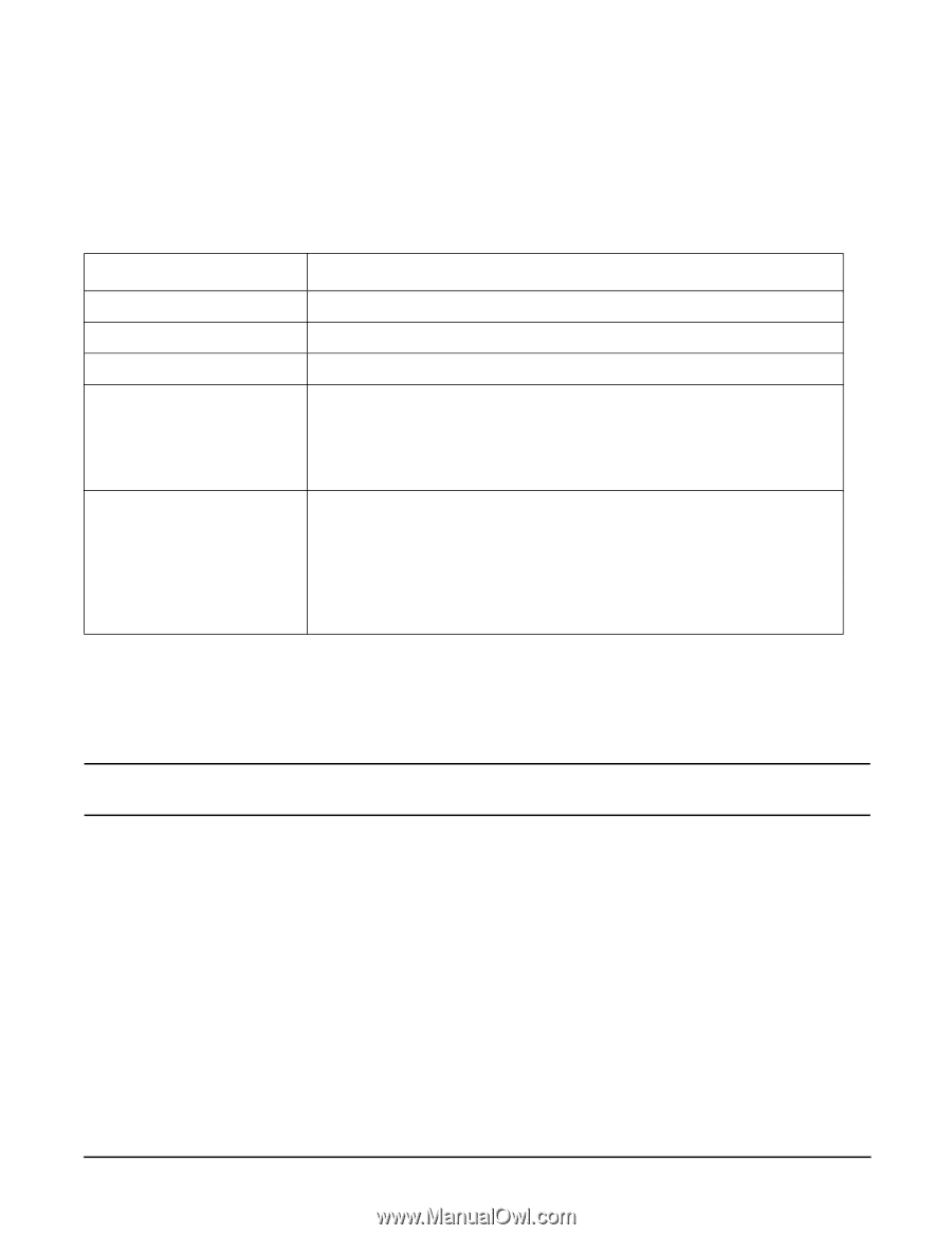
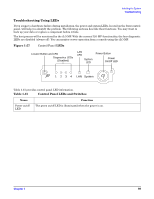
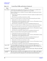
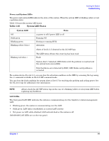
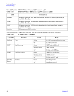
Installing the System Troubleshooting Power and System LEDs The power and system LEDs indicate the state of the system. When the system LED is blinking yellow or red, a problem exists. Table 1-16 provides system LED states. Table 1-16 System LED States System LED Off Solid green Blinking green Blinking yellow (1/sec.) State ac power is off if power LED is off. Running OS. Booting or running BCH. Attention: Alerts of levels 3-5 detected in the iLO MP logs. Blinking red (2/sec.) The LED turns off once the event log has been read. Fault: System Alert 7 detected, LED blinks until the problem is resolved and the system boots successfully . Fatal hardware error detected by BMC, LED blinks until problem is corrected. For system alerts of levels 3-5, you can clear the attention condition on the LED by accessing the logs using the sl command available in the iLO MP command mode. You can clear the fault condition for system alerts of level 7 by resolving the problem and cycling power. See the SL error logs for additional error information. NOTE Always check the iLO MP status logs in the case of a blinking yellow or red system LED before replacing any hardware. LAN LEDs The front panel LAN LED indicates the system is communicating over the Gigabit or system management LAN: • Blinking green: the system is communicating over the LAN. • Solid green: LAN link is established; no current LAN activity. • Not green: no LAN cable attached; LAN network dead or the system is off. 10/100/1000 LAN LEDs are on the rear panel. Chapter 1 91
-
 1
1 -
2
-
3
-
4
-
5
-
6
-
7
-
8
-
9
-
10
-
11
-
12
-
13
-
14
-
15
-
16
-
17
-
18
-
19
-
20
-
21
-
22
-
23
-
24
-
25
-
26
-
27
-
28
-
29
-
30
-
31
-
32
-
33
-
34
-
35
-
36
-
37
-
38
-
39
-
40
-
41
-
42
-
43
-
44
-
45
-
46
-
47
-
48
-
49
-
50
-
51
-
52
-
53
-
54
-
55
-
56
-
57
-
58
-
59
-
60
-
61
-
62
-
63
-
64
-
65
-
66
-
67
-
68
-
69
-
70
-
71
-
72
-
73
-
74
-
75
-
76
-
77
-
78
-
79
-
80
-
81
-
82
-
83
-
84
-
85
-
 86
86 -
 87
87 -
 88
88 -
 89
89 -
 90
90 -
 91
91 -
 92
92 -
 93
93 -
 94
94 -
 95
95 -
 96
96
 |
 |