HP rp3440 Installation Guide, Seventh Edition - HP 9000 rp3410 and HP 9000 rp3 - Page 31
Removing the Top Cover, on a Pedestal-Mounted Server, Step 4.
 |
View all HP rp3440 manuals
Add to My Manuals
Save this manual to your list of manuals |
Page 31 highlights
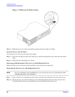
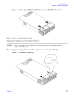
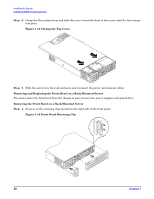
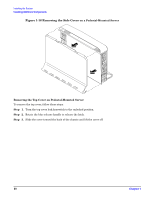
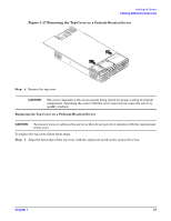
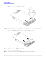
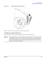
Installing the System Installing Additional Components Figure 1-17 Removing the Top Cover on a Pedestal-Mounted Server Step 4. Remove the top cover. CAUTION The server depends on the access panels being closed for proper cooling of internal components. Operating the server with the cover removed can cause the server to quickly overheat. Replacing the Top Cover on a Pedestal-Mounted Server CAUTION Secure any wires or cables in the server so they do not get cut or interfere with the replacement of the cover. To replace the top cover, follow these steps: Step 1. Align the front edge of the top cover with the alignment mark on the optical drive bay. Chapter 1 31
-
 1
1 -
2
-
3
-
4
-
5
-
6
-
7
-
8
-
9
-
10
-
11
-
12
-
13
-
14
-
15
-
16
-
17
-
18
-
19
-
20
-
21
-
22
-
23
-
24
-
25
-
 26
26 -
 27
27 -
 28
28 -
 29
29 -
 30
30 -
 31
31 -
 32
32 -
 33
33 -
 34
34 -
 35
35 -
 36
36 -
37
-
38
-
39
-
40
-
41
-
42
-
43
-
44
-
45
-
46
-
47
-
48
-
49
-
50
-
51
-
52
-
53
-
54
-
55
-
56
-
57
-
58
-
59
-
60
-
61
-
62
-
63
-
64
-
65
-
66
-
67
-
68
-
69
-
70
-
71
-
72
-
73
-
74
-
75
-
76
-
77
-
78
-
79
-
80
-
81
-
82
-
83
-
84
-
85
-
86
-
87
-
88
-
89
-
90
-
91
-
92
-
93
-
94
-
95
-
96
 |
 |
Installing the System
Installing Additional Components
Chapter 1
31
Figure 1-17 Removing the Top Cover
on a Pedestal-Mounted Server
Step 4.
Remove the top cover.
CAUTION
The server depends on the access panels being closed for proper cooling of internal
components. Operating the server with the cover removed can cause the server to
quickly overheat.
Replacing the Top Cover on a Pedestal-Mounted Server
CAUTION
Secure any wires or cables in the server so they do not get cut or interfere with the replacement
of the cover.
To replace the top cover, follow these steps:
Step 1.
Align the front edge of the top cover with the alignment mark on the optical drive bay.