HP rp3440 Installation Guide, Seventh Edition - HP 9000 rp3410 and HP 9000 rp3 - Page 49
System Firmware Requirements, Installation Procedure, Step 1., CAUTION - firmware download
 |
View all HP rp3440 manuals
Add to My Manuals
Save this manual to your list of manuals |
Page 49 highlights
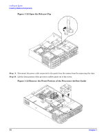
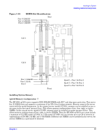
Installing the System Installing Additional Components In order to use the chip spare functionality, only DIMMs built with x4 SDRAM parts can be used, and these DIMMs must be loaded in quads (two DIMMs per memory cell, loaded in the same location in each memory cell). System Firmware Requirements If you are using 4 GB DIMMs in a HP 9000 rp3440 server, system firmware must be greater than revision 44.24. Use the BCH FV command, or the iLO MP SR command to display the system firmware revision status. If necessary, use the iLO MP SR command to upgrade system firmware. (Detailed instructions are downloaded with the upgrade.) Installation Procedure To install DIMMs, follow these steps: Step 1. Power off the server and disconnect all power and external cables. Step 2. Remove the server cover. (See "Removing and Replacing Server Covers and Bezels" on page 25.) Step 3. Remove the memory airflow guide. (See "Removing the Memory Airflow Guide" on page 41.) CAUTION To ensure that memory modules are not damaged during removal or installation, power off the server and unplug the power cord from the ac power outlet. Wait until the LED on the back of the power supply turns off before removing or installing memory. Step 4. Locate the slot into which the DIMM will be installed. Holding the memory module by its left and right edges, insert the module into the socket (Figure 1-36.) NOTE The memory modules are keyed and can only be inserted in one direction. When the module is correctly seated, the retainer clips will return to their fully upright position. Snap the clips firmly into place to ensure that the DIMMs are seated properly. Step 5. Evenly push down firmly on each end of the DIMM until it seats in the socket. Ensure the extraction levers are in the closed position. Chapter 1 49
-
 1
1 -
2
-
3
-
4
-
5
-
6
-
7
-
8
-
9
-
10
-
11
-
12
-
13
-
14
-
15
-
16
-
17
-
18
-
19
-
20
-
21
-
22
-
23
-
24
-
25
-
26
-
27
-
28
-
29
-
30
-
31
-
32
-
33
-
34
-
35
-
36
-
37
-
38
-
39
-
40
-
41
-
42
-
43
-
 44
44 -
 45
45 -
 46
46 -
 47
47 -
 48
48 -
 49
49 -
 50
50 -
 51
51 -
 52
52 -
 53
53 -
 54
54 -
55
-
56
-
57
-
58
-
59
-
60
-
61
-
62
-
63
-
64
-
65
-
66
-
67
-
68
-
69
-
70
-
71
-
72
-
73
-
74
-
75
-
76
-
77
-
78
-
79
-
80
-
81
-
82
-
83
-
84
-
85
-
86
-
87
-
88
-
89
-
90
-
91
-
92
-
93
-
94
-
95
-
96
 |
 |