HP rp3440 Installation Guide, Seventh Edition - HP 9000 rp3410 and HP 9000 rp3 - Page 89
Troubleshooting Using LEDs, Table 1-15, Control Panel LEDs and Switches
 |
View all HP rp3440 manuals
Add to My Manuals
Save this manual to your list of manuals |
Page 89 highlights
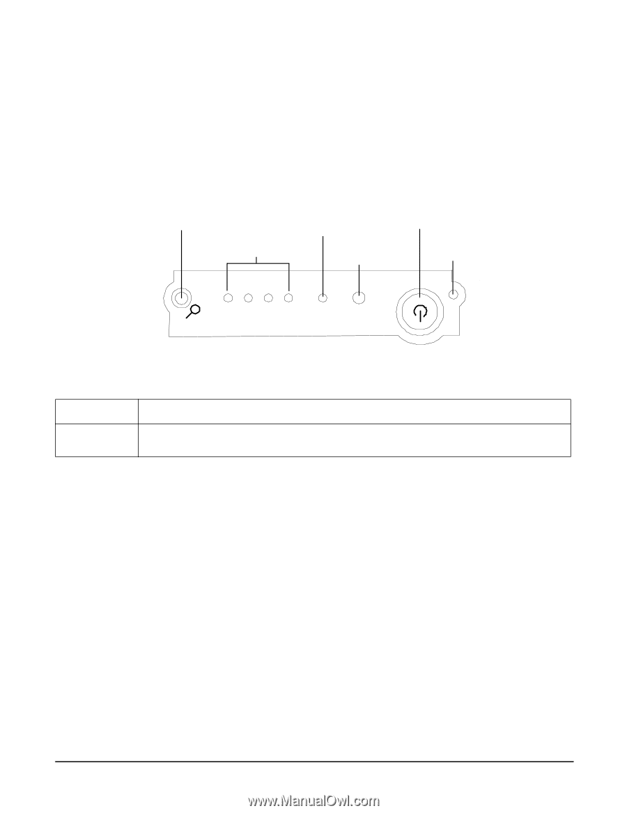
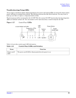
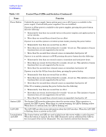
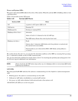
Installing the System Troubleshooting Troubleshooting Using LEDs If you suspect a hardware failure during installation, the power and system LEDs, located on the front control panel, will help you identify the problem. The following sections describe their functions. You may want to back up your data or replace a component before it fails. The boot process will be monitored by the iLO MP. With the current ILO MP functionality, the four diagnostic LEDs are disabled (always off). You can monitor server operation from a console using the iLO MP. Figure 1-57 Control Panel LEDs Locator Button and LED Diagnostics LEDs (Disabled) LAN LED System LED Power Button Power On/Off LED 1 2 3 4 LAN System Table 1-15 provides control panel LED information. Table 1-15 Control Panel LEDs and Switches Name Power on/off LED Function The green on/off LED is illuminated when the power is on. Chapter 1 89
-
 1
1 -
2
-
3
-
4
-
5
-
6
-
7
-
8
-
9
-
10
-
11
-
12
-
13
-
14
-
15
-
16
-
17
-
18
-
19
-
20
-
21
-
22
-
23
-
24
-
25
-
26
-
27
-
28
-
29
-
30
-
31
-
32
-
33
-
34
-
35
-
36
-
37
-
38
-
39
-
40
-
41
-
42
-
43
-
44
-
45
-
46
-
47
-
48
-
49
-
50
-
51
-
52
-
53
-
54
-
55
-
56
-
57
-
58
-
59
-
60
-
61
-
62
-
63
-
64
-
65
-
66
-
67
-
68
-
69
-
70
-
71
-
72
-
73
-
74
-
75
-
76
-
77
-
78
-
79
-
80
-
81
-
82
-
83
-
 84
84 -
 85
85 -
 86
86 -
 87
87 -
 88
88 -
 89
89 -
 90
90 -
 91
91 -
 92
92 -
 93
93 -
 94
94 -
95
-
96
 |
 |