HP rp3440 Installation Guide, Seventh Edition - HP 9000 rp3410 and HP 9000 rp3 - Page 40
Removing and Replacing Airflow Guides, Installing the DVD Drive, Step 1.
 |
View all HP rp3440 manuals
Add to My Manuals
Save this manual to your list of manuals |
Page 40 highlights
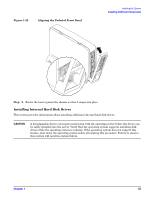
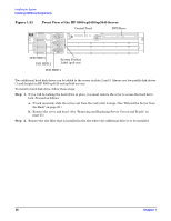
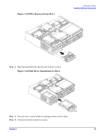
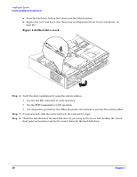
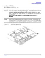
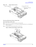
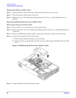
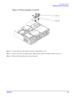
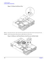
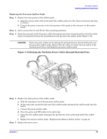
Installing the System Installing Additional Components Installing the DVD Drive To install a DVD drive, follow these steps: Step 1. Power off the server and disconnect power and external cables. Step 2. Remove the front bezel and cover. (See "Removing and Replacing Server Covers and Bezels" on page 25.) Step 3. If a removable media drive has not previously been installed in the server, the drive slot will be covered with a DVD drive filler. Remove the DVD drive filler. Step 4. Slide the drive into the drive bay until it stops sliding and the retaining clips on both sides of the drive snap into place (Figure 1-27). Step 5. Connect the IDE cable on the back of the drive (Figure 1-27). Step 6. Replace the cover and bezel. (See "Removing and Replacing Server Covers and Bezels" on page 25.) Step 7. Reconnect the power and external cables and turn on the server. Step 8. Verify the drive operation by using the system utilities. • Use the iLO MP commands to verify operation. • Use the BCH commands to verify operation. • Use diagnostics provided by the offline diagnostic environment to exercise the newly installed module. Removing and Replacing Airflow Guides You must remove airflow guides before installing processors or memory. The server has the following airflow guides: • The processor airflow guide ensures that the proper volume of air for cooling the dual processor module power pods, processor module(s), and voltage regulator module(s) flows over these components. You must remove the processor airflow guide before removing or installing a dual processor module. • The memory airflow guide ensures that the proper volume of air flows over the memory DIMMs to cool them. You must remove the memory airflow guide to access memory DIMMs and sockets. NOTE Air flows through the server from front to back. 40 Chapter 1
-
 1
1 -
2
-
3
-
4
-
5
-
6
-
7
-
8
-
9
-
10
-
11
-
12
-
13
-
14
-
15
-
16
-
17
-
18
-
19
-
20
-
21
-
22
-
23
-
24
-
25
-
26
-
27
-
28
-
29
-
30
-
31
-
32
-
33
-
34
-
 35
35 -
 36
36 -
 37
37 -
 38
38 -
 39
39 -
 40
40 -
 41
41 -
 42
42 -
 43
43 -
 44
44 -
 45
45 -
46
-
47
-
48
-
49
-
50
-
51
-
52
-
53
-
54
-
55
-
56
-
57
-
58
-
59
-
60
-
61
-
62
-
63
-
64
-
65
-
66
-
67
-
68
-
69
-
70
-
71
-
72
-
73
-
74
-
75
-
76
-
77
-
78
-
79
-
80
-
81
-
82
-
83
-
84
-
85
-
86
-
87
-
88
-
89
-
90
-
91
-
92
-
93
-
94
-
95
-
96
 |
 |