HP rp3440 Installation Guide, Seventh Edition - HP 9000 rp3410 and HP 9000 rp3 - Page 60
Aligning the Processor Module Power Pod, Step 13.
 |
View all HP rp3440 manuals
Add to My Manuals
Save this manual to your list of manuals |
Page 60 highlights
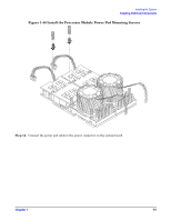
Installing the System Installing Additional Components Figure 1-48 Aligning the Processor Module Power Pod Step 13. Align the two mounting screw holes on the power pod module with the screw holes in the shims on the system board's metal mounting bracket. Screw in the power pod module mounting screws. (Use the screws removed in step 11.) 60 Chapter 1
-
 1
1 -
2
-
3
-
4
-
5
-
6
-
7
-
8
-
9
-
10
-
11
-
12
-
13
-
14
-
15
-
16
-
17
-
18
-
19
-
20
-
21
-
22
-
23
-
24
-
25
-
26
-
27
-
28
-
29
-
30
-
31
-
32
-
33
-
34
-
35
-
36
-
37
-
38
-
39
-
40
-
41
-
42
-
43
-
44
-
45
-
46
-
47
-
48
-
49
-
50
-
51
-
52
-
53
-
54
-
 55
55 -
 56
56 -
 57
57 -
 58
58 -
 59
59 -
 60
60 -
 61
61 -
 62
62 -
 63
63 -
 64
64 -
 65
65 -
66
-
67
-
68
-
69
-
70
-
71
-
72
-
73
-
74
-
75
-
76
-
77
-
78
-
79
-
80
-
81
-
82
-
83
-
84
-
85
-
86
-
87
-
88
-
89
-
90
-
91
-
92
-
93
-
94
-
95
-
96
 |
 |
Installing the System
Installing Additional Components
Chapter 1
60
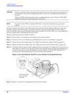
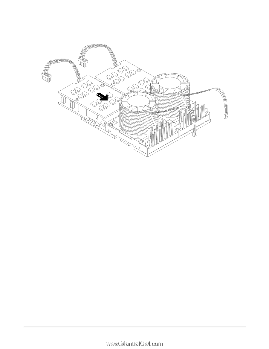
Figure 1-48 Aligning the Processor Module Power Pod
Step 13.
Align the two mounting screw holes on the power pod module with the screw holes in the shims on
the system board’s metal mounting bracket. Screw in the power pod module mounting screws. (Use
the screws removed in step 11.)