HP rp3440 Installation Guide, Seventh Edition - HP 9000 rp3410 and HP 9000 rp3 - Page 25
Installing Additional Components, Removing and Replacing Server Covers and Bezels - - weight
 |
View all HP rp3440 manuals
Add to My Manuals
Save this manual to your list of manuals |
Page 25 highlights
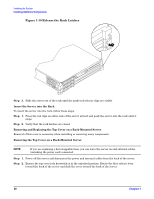
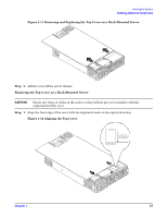
Installing the System Installing Additional Components Installing Additional Components This section describes how to install server components that are not installed before delivery. Removing and Replacing Server Covers and Bezels To upgrade, remove, or replace most server components, you must first remove the covers from the server chassis. This section explains how to remove and replace the covers for both rack and pedestal-mounted configurations. WARNING Do not remove the server cover without first turning the server off and unplugging the power cord from the outlet or power protection device unless you are only replacing a hot-swappable fan. Always replace the cover before turning the server on. Rack-Mounted Server To access the internal components on a rack-mounted server, pull the server out onto the rail guides and remove the top cover. Accessing a Rack-Mounted Server HP 9000 rp3410 and rp3440 servers are designed to be rack mounted. The following procedure explains how to gain access to a server that is mounted in an approved rack. For slide installation instructions, see the Installation Guide, Mid-Weight Slide Kit (HP part number 5065-7291). This document can be accessed on the Web at: http://www.hp.com/racksolutions. WARNING Ensure that all anti-tip features (front and rear anti-tip feet installed; adequate ballast properly placed; and so on) are employed prior to extending the server. Extend the Server from the Rack NOTE Ensure that there is enough area (approximately 1.5 meters {4.5 ft.}) to fully extend the server out the front to work on it. To extend the server from the rack, follow these steps: NOTE If you are replacing a hot-swappable item, you can leave the server on and external cables (including the power cord) connected. Step 1. Power off the server and disconnect the power and external cables from the back of the server. Step 2. Release the rack latches by rotating them outward. Chapter 1 25
-
 1
1 -
2
-
3
-
4
-
5
-
6
-
7
-
8
-
9
-
10
-
11
-
12
-
13
-
14
-
15
-
16
-
17
-
18
-
19
-
 20
20 -
 21
21 -
 22
22 -
 23
23 -
 24
24 -
 25
25 -
 26
26 -
 27
27 -
 28
28 -
 29
29 -
 30
30 -
31
-
32
-
33
-
34
-
35
-
36
-
37
-
38
-
39
-
40
-
41
-
42
-
43
-
44
-
45
-
46
-
47
-
48
-
49
-
50
-
51
-
52
-
53
-
54
-
55
-
56
-
57
-
58
-
59
-
60
-
61
-
62
-
63
-
64
-
65
-
66
-
67
-
68
-
69
-
70
-
71
-
72
-
73
-
74
-
75
-
76
-
77
-
78
-
79
-
80
-
81
-
82
-
83
-
84
-
85
-
86
-
87
-
88
-
89
-
90
-
91
-
92
-
93
-
94
-
95
-
96
 |
 |