HP rp3440 Installation Guide, Seventh Edition - HP 9000 rp3410 and HP 9000 rp3 - Page 52
Installing PCI Cards, Removing the PCI Card Cage Cover
 |
View all HP rp3440 manuals
Add to My Manuals
Save this manual to your list of manuals |
Page 52 highlights
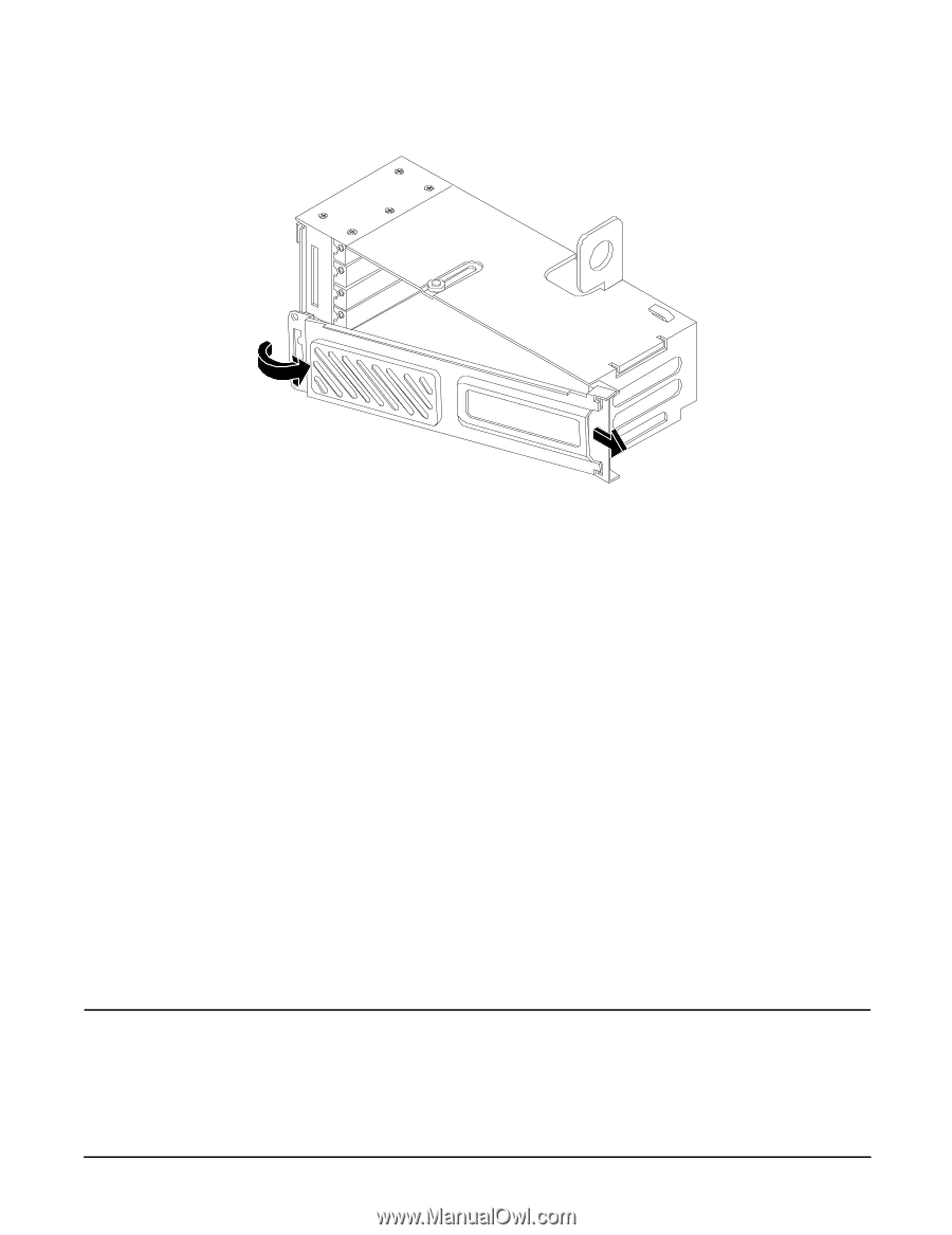
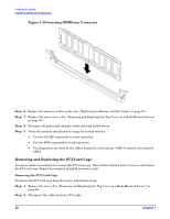
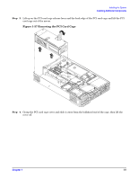
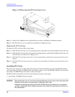
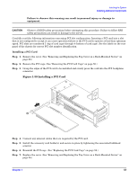
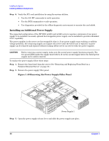
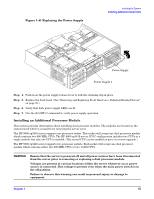
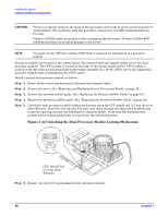
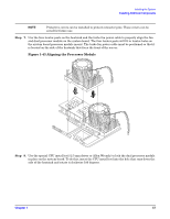
Installing the System Installing Additional Components Figure 1-38 Removing the PCI Card Cage Cover Step 5. Unscrew the bulkhead screw that holds the accessory card holder (if installed) in place. Step 6. The PCI slots are now accessible for installation of additional cards. Replacing the PCI Card Cage To replace the PCI card cage, follow these steps: Step 1. Hold the PCI card cage cover in mounting position and slide it toward the bulkhead end of the cage. Step 2. Hold the PCI card cage above the chassis mounting position, such that the bulkhead end of the cage is toward the rear of the server. (Figure 1-37.) Step 3. Hold the PCI card cage release lever in the raised position and lower the card cage into the server chassis. Step 4. Press the PCI card cage release lever into the lowered position to lock the card cage into the server chassis. Installing PCI Cards The server can contain up to 4 PCI cards. PCI cards are located in the PCI card cage. The HP 9000 rp3410 server provides two 64-bit, 133 MHz PCI-X card sockets as slots 1 and 2. The HP 9000 rp3440 server provides four 64-bit, 133 MHz PCI-X card sockets as slots 1 through 4. HP 9000 rp3410 and rp3440 servers have the following accessory card sockets: • Four 64-bit, 133 MHz PCI-X card sockets. WARNING Ensure that the server is powered off and all power sources have been disconnected from the server prior to removing or replacing a PCI card. Voltages are present at various locations within the server whenever an ac power source is connected. This voltage is present even when the main power switch is in the off position. 52 Chapter 1
-
 1
1 -
2
-
3
-
4
-
5
-
6
-
7
-
8
-
9
-
10
-
11
-
12
-
13
-
14
-
15
-
16
-
17
-
18
-
19
-
20
-
21
-
22
-
23
-
24
-
25
-
26
-
27
-
28
-
29
-
30
-
31
-
32
-
33
-
34
-
35
-
36
-
37
-
38
-
39
-
40
-
41
-
42
-
43
-
44
-
45
-
46
-
 47
47 -
 48
48 -
 49
49 -
 50
50 -
 51
51 -
 52
52 -
 53
53 -
 54
54 -
 55
55 -
 56
56 -
 57
57 -
58
-
59
-
60
-
61
-
62
-
63
-
64
-
65
-
66
-
67
-
68
-
69
-
70
-
71
-
72
-
73
-
74
-
75
-
76
-
77
-
78
-
79
-
80
-
81
-
82
-
83
-
84
-
85
-
86
-
87
-
88
-
89
-
90
-
91
-
92
-
93
-
94
-
95
-
96
 |
 |